Welcome to Laser Pointer Forums - discuss green laser pointers, blue laser pointers, and all types of lasers

LPF Donation via Stripe | LPF Donation - Other Methods

Links below open in new window

ArcticMyst Security by Avery

Pinout for 445 nm diode a130

Joined
Jul 9, 2009
Messages
51
Points
0
Hey guys,

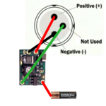
I was just wondering if anyone had a pinout for the casio a130 diode. Like which pin is positive and which is negative or unused. Thanks alot!


Morgan

0
Joined
Feb 5, 2009
Messages
2,174
Points
0
Look up any Bluray diode pinout in the, "Diode Compilation", thread. PHR, GGW, etc... These blues are the same.

M
:)
 
Joined
Apr 29, 2008
Messages
1,562
Points
48
brde9.jpg

From http://laserpointerforums.com/f42/meta-topic-pinout-performance-actual-ld-26417.html
 
Joined
Feb 23, 2008
Messages
2,832
Points
48
dont hook the case pin to the -.. your not supposed to if you use any of the newer flex drives or micro boost. you have to use a piece of wire from the case pin to the - input on the driver.
 
Joined
Dec 29, 2009
Messages
3,136
Points
63
you are saying if I want to use the case pin on the diode as the power source ground point for the driver that is fine. Just don't use the case pin as the - connection for the LD output on the driver.
 
Joined
Jan 11, 2008
Messages
671
Points
0
The case pin can be connected to negative (-) voltage right? Otherwise most of the DIY flashlight builds wouldn't work. You still have to connect the negative pin though.
 

Kevlar

0
Joined
Apr 26, 2010
Messages
1,353
Points
48
dont hook the case pin to the -.. your not supposed to if you use any of the newer flex drives or micro boost. you have to use a piece of wire from the case pin to the - input on the driver.

This is how I just did my Ehgemus build, case negative. I wanted to make sure so I checked with Ehgemus, this is the diagram he sent me.

Or you could connect a wire from the - input on the driver to the host
 

Attachments

  • Blu diode and boost driver wiring.png
    Blu diode and boost driver wiring.png
    22.8 KB · Views: 7,513

Kevlar

0
Joined
Apr 26, 2010
Messages
1,353
Points
48
Here is how I did it with my build..

I was looking at your build too ReNNo in another thread. I like where you connected the case pin to the driver. That negative input on the driver goes right up the side...
 

ReNNo

0
Joined
Mar 27, 2009
Messages
589
Points
0
I know...there is connection pad just where cathode pad is.. but it's more difficult to solder shorter wire, and I didn't want to lap isolation layer.
 
Joined
Aug 15, 2009
Messages
1,443
Points
48
Does anyone know if it is possible to leave the case floating with respect to the diode? I build a driver that can be used only for case positive diodes, but can I just leave the case at a voltage different from both + and -? I don't wanna blow up my diode.
 
Joined
Nov 5, 2007
Messages
4,919
Points
83
dont hook the case pin to the -.. your not supposed to if you use any of the newer flex drives or micro boost. you have to use a piece of wire from the case pin to the - input on the driver.

I think this only applies to the micro-boost, groove, and rckstr. Can't you still solder the case pin to the negative pin for case negative devices with the Flexdrive V5? I am pretty sure you can.
 
Joined
Jan 11, 2008
Messages
671
Points
0
Does anyone know if it is possible to leave the case floating with respect to the diode? I build a driver that can be used only for case positive diodes, but can I just leave the case at a voltage different from both + and -? I don't wanna blow up my diode.

Yes you are correct, the voltage of the case pin does not matter.
 
Joined
Aug 27, 2010
Messages
30
Points
0
Can someone please post a photo of how to connect an A-140 diode to a V5 flexdrive. I have searched everywhere but there is no 'correct' way.


Top