Welcome to Laser Pointer Forums - discuss green laser pointers, blue laser pointers, and all types of lasers

Buy Site Supporter Role (remove some ads) | LPF Donations

Links below open in new window

FrozenGate by Avery

Pinout for 445 nm diode a130

Joined
Jul 9, 2009
Messages
51
Points
0
Hey guys,

I was just wondering if anyone had a pinout for the casio a130 diode. Like which pin is positive and which is negative or unused. Thanks alot!


Look up any Bluray diode pinout in the, "Diode Compilation", thread. PHR, GGW, etc... These blues are the same.

M
:)
 
brde9.jpg

From http://laserpointerforums.com/f42/meta-topic-pinout-performance-actual-ld-26417.html
 
dont hook the case pin to the -.. your not supposed to if you use any of the newer flex drives or micro boost. you have to use a piece of wire from the case pin to the - input on the driver.
 
you are saying if I want to use the case pin on the diode as the power source ground point for the driver that is fine. Just don't use the case pin as the - connection for the LD output on the driver.
 
The case pin can be connected to negative (-) voltage right? Otherwise most of the DIY flashlight builds wouldn't work. You still have to connect the negative pin though.
 
dont hook the case pin to the -.. your not supposed to if you use any of the newer flex drives or micro boost. you have to use a piece of wire from the case pin to the - input on the driver.

This is how I just did my Ehgemus build, case negative. I wanted to make sure so I checked with Ehgemus, this is the diagram he sent me.

Or you could connect a wire from the - input on the driver to the host
 

Attachments

  • Blu diode and boost driver wiring.png
    Blu diode and boost driver wiring.png
    22.8 KB · Views: 7,513
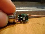
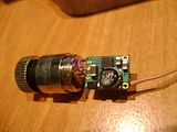
Here is how I did it with my build..

I was looking at your build too ReNNo in another thread. I like where you connected the case pin to the driver. That negative input on the driver goes right up the side...
 
I know...there is connection pad just where cathode pad is.. but it's more difficult to solder shorter wire, and I didn't want to lap isolation layer.
 
Does anyone know if it is possible to leave the case floating with respect to the diode? I build a driver that can be used only for case positive diodes, but can I just leave the case at a voltage different from both + and -? I don't wanna blow up my diode.
 
dont hook the case pin to the -.. your not supposed to if you use any of the newer flex drives or micro boost. you have to use a piece of wire from the case pin to the - input on the driver.

I think this only applies to the micro-boost, groove, and rckstr. Can't you still solder the case pin to the negative pin for case negative devices with the Flexdrive V5? I am pretty sure you can.
 
Does anyone know if it is possible to leave the case floating with respect to the diode? I build a driver that can be used only for case positive diodes, but can I just leave the case at a voltage different from both + and -? I don't wanna blow up my diode.

Yes you are correct, the voltage of the case pin does not matter.
 
Can someone please post a photo of how to connect an A-140 diode to a V5 flexdrive. I have searched everywhere but there is no 'correct' way.


Back
Top