Welcome to Laser Pointer Forums - discuss green laser pointers, blue laser pointers, and all types of lasers

LPF Donation via Stripe | LPF Donation - Other Methods

Links below open in new window

ArcticMyst Security by Avery

NUBM44 6W+ 450nm Laser Diode

Joined
Jun 26, 2015
Messages
31
Points
8
Do you have a bench top power supply?

That was not clear?

Yeah, pretty nice one :eg:
0-15V 0-60A
0-30V 0-30A
0-60v 0-15A
It has a 3 way switch I must choose from
It's a switching power supply. I know that has its cons. But I am happy with it :)

Ow, I thought it was called a lab supply, my bad
 
Last edited:


Joined
Jun 26, 2015
Messages
31
Points
8
Ok so you know your diode is good, it's just the driver that's possibly overheating?
Yeah :)

Just read my post all the way down page 24. Post #384
edit: here it is:
Thank you Alan, very helpful! :)

A few test results:

I bought the driver set @ 4500mA and it was already soldered to the diode when it arrived.

I was playing with the laser this afternoon and decided to add an ammeter (multimeter) between the driver and the diode.
Lab supply was set @ 8.0V and deliverd 2.4-2.5A (I set voltage, current is left unlimited.)
Surprisingly the multimeter reads 3.6xx mA to the laser diode.
I don't know why that is. I'm not accusing anyone, maybe I touched the potmeter with my fingers when handling it.
I soon realized that increased temperature on the driver gives a higher amperage to the laser.
With a little screwdriver I set the driver @ 4.1xx mA (and I realized how sensitive that potmeter is)
Amperage quickly ramps up. After ~5 minutes the driver delivers 4.620mA and the 445gram module is 51degree Celsius (123.8 degrees Fahrenheit). Measured with IR-thermometer gun pointed close to a piece of black tape that I added to the heatsink. Room temperature is 26 degree Celsius (78.8 degrees Fahrenheit, yes its a nice summer here :))
Lab supply was of course still set @ 8.0V and delivered 3.0 Amps near the end

I disconnected power.
And reconnect after ~1 minute with the heatsink still quite warm and driver having the same temperature as the heatsink now.

It takes 1-2 minutes for the driver to start from 4.1xx mA and ramp up to +4.6xx mA.
Kind of a heat-sensitive driver, right?
I hope it's not that little aluminium holder that is causing it.
I will make one out of plastic tonight.

Any thoughts?


I called it a lab supply
My bad

I think the issue is heat.
Here is a crazy thought:
Is it possible that the heat from the driver is lowering the resistance in the potmeter? because the variable resistor in the potentiometer is made out of graphite. And graphite conducts electricity better when it gets hot.
I do know that the potentiometer on the driver is very sensitive when it comes to adjusting. What do you guys think?

But where does the heat come from? or is it that simple that the driver is not heatsinked very well and just heats up the whole driver? That the only contact between the 8pin and heatsink is just not enough?

Yes the whole 8-pin chip surface area is touching the heatsink. it is mounted nice and flat.

The reason I didn't fill the whole thing up with Artic Silver 5 is because if that is not the problem, then I have a driver completely covered with that crap for no reason.
I also don't have much left and even the smallest syringe is pretty expensive here.

I think its heat in combination with insufficient heat sinking

I talk too much
 
Last edited:
Joined
Jan 29, 2014
Messages
12,031
Points
113
I believe I had a problem with one of my builds due to the sense resistor getting hot causing the output to increase a few hundred ma above where I set the driver to operate at, either that or the coil getting hot also had some effect to the driver to cause that too, not sure.
 
Joined
Jul 10, 2015
Messages
9,908
Points
113
I know I will get flamed for this but it works for me.
I completely cocoon my drivers in thermal paste that has the consistency of thick toothpaste and dries to the consistency of firm clay.
I have done this with over a dozen different models of drivers and had no problems with it, except 1 osram diode that went led with less than 5 hours of total runtime on it ( 2-3 minutes per run ) but I blame the diode as it was still led ( very dim dot ) after removal, the driver did not survive removal and that is one problem with my method, it is a permanent driver mounting method.
I cocoon the drivers in this paste in the 12mm hole behind the diode module or in a separate 12mm module behind the diode module or I fill the module housing behind the diode when the driver is attached to the diode.
I have had great success with Chinese 532 dpss modules by cocooning the drivers as well.
Anyway if you do this you do so at your own risk and I'm sure many will explain to me why it is wrong, all I can say is it has worked well for me.

50ml Thermal Fujik Silicone Adhesive Glue Grease Coupling CPU Heatsink Compound | eBay
 
Last edited:

DTR

0
Joined
Jun 24, 2010
Messages
5,684
Points
113
Yes this is correct. The SXD drivers do drift up about 200-300mA from cold start when running over 4A but then hold steady. You should not have a problem setting them as it gets to full current very quickly. Angelos had made these drivers capable of a exaggerated slow start which I had him turn off on the ones he sends me where it goes to 50% right away and then over depending on how long it is set slowly increases to full current to reduce startup shock to the diode. I think this is a residual of the feature being turned make the start as fast as possible. He can probably comment further on the specifics of it.:beer:
 
Joined
Jul 10, 2015
Messages
9,908
Points
113
Yes this is correct. The SXD drivers do drift up about 200-300mA from cold start when running over 4A but then hold steady. You should not have a problem setting them as it gets to full current very quickly. Angelos had made these drivers capable of a exaggerated slow start which I had him turn off on the ones he sends me where it goes to 50% right away and then over depending on how long it is set slowly increases to full current to reduce startup shock to the diode. I think this is a residual of the feature being turned make the start as fast as possible. He can probably comment further on the specifics of it.:beer:

Good looking build DutchLaser, Now how about some beamshots.
p.s. How do I insert a large pic?
 

Attachments

  • SANY0220.JPG
    SANY0220.JPG
    180.7 KB · Views: 884
Last edited:
Joined
Jun 22, 2011
Messages
2,431
Points
83
You do know you can edit your posts, right? No need to delete the previous and add a new one ten times in a row.
 
Joined
Jun 26, 2015
Messages
31
Points
8
Good looking build DutchLaser, Now how about some beamshots.
p.s. How do I insert a large pic?
Thank you, yours are nice too :beer:

Why don't you upload pics on tinypic.com (for instance) and paste the link between this:
[IMG*]http://the link that the upload website provides.jpg[/IMG*]

minus the '*'

I advise to upload 800x600 resolution, maybe little bigger, not too much
 
Last edited:
Joined
Jan 8, 2009
Messages
3,145
Points
83
How about you 2 post your own build threads and leave this as an info gathering on the diode I'm going to unsubscribe as this seems to be moot now. Yes nice builds.
 
Joined
Jun 26, 2015
Messages
31
Points
8
Yes this is correct. The SXD drivers do drift up about 200-300mA from cold start when running over 4A but then hold steady. You should not have a problem setting them as it gets to full current very quickly. Angelos had made these drivers capable of a exaggerated slow start which I had him turn off on the ones he sends me where it goes to 50% right away and then over depending on how long it is set slowly increases to full current to reduce startup shock to the diode. I think this is a residual of the feature being turned make the start as fast as possible. He can probably comment further on the specifics of it.:beer:

I really like the stuff you sold :thanks:

I have a question about wavelength.
I have no equipment to measure wavelength unfortunately, but I can compare with my other two blue lasers.

My M140 is not relevant, forget that one. Too much purple.
The other one is a PLTB450b that I drive @ ~1800mA.
The NUBM44 appears to be more 'light-blue' than the PLTB450b when I light up a dark room with white walls
The PLTB450b consumes 200mA more then the maximum allowed amperage according to Osrams datasheet. And the wavelenght of the PLTB450b can peak to 460nm according to that same datasheet.
What do you know about the wavelengths of these diodes? Can you verify/clearify somewhat too me?

I would like to get a number in nm's so I can compare if it is still worth money and effort to get the other diode (the 465nm one)


Edit:
Never mind, I remember Planters saying something about it on youtube
The PLTB450b is probably just not emitting 460nm
 
Last edited:
Joined
Jun 26, 2015
Messages
31
Points
8
How about you 2 post your own build threads and leave this as an info gathering on the diode I'm going to unsubscribe as this seems to be moot now. Yes nice builds.

sorry, one thing lead to an other.
I would like to do that but I think I was getting flamed for double posting.
Build is finished...
I'll visit you guys again in 2017 or so when the new generation diodes are ready :na:
 
Last edited:
Joined
Jul 10, 2015
Messages
9,908
Points
113
sorry, one thing lead to an other.
I would like to do that but I think I was getting flamed for double posting.
Build is finished.

POST # 214 on PAGE # 14 has graphs on power and wavelength.
I get the idea that people here like to have uncluttered access to info on the specific topic, we should post our build pics in a new thread because if everyone did it here the thread would fill up.
Try reading the butthurt thing at the bottom of Janders last page.
They also want everyone to read and learn for themselves otherwise the thread fills up with duplicate questions, it seems picky but it's not really because it makes sense.
Lets learn to post our own threads and then we can talk all we want.
Do post a thread with beam shots and make sure to try a 3 element lens.
Oh and Hell Yes you want a NUBM07E when then are available, don't buy from that guy in china unless you want to wait 8 weeks.
 
Last edited:

DTR

0
Joined
Jun 24, 2010
Messages
5,684
Points
113
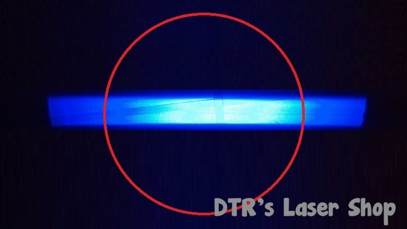
@ DutchLaser WOW I just put in a G9.....at .5 meters yes it's still strong but at 7 meters the tightest line is 2 times as wide and 2 times as long as with the 3 element. That's .25 the energy density so even with a 25% loss up front....just try a 3 element, you will see the difference, even with the power loss you still have 4x the energy density and you will set fire to any wood up close with a 3 element faster.

There may be a slight bump in power density but for the most part this is what happens with the three element lens. Everything outside the circle is clipped due to the longer focal length which makes the spot look smaller but instead of folding that energy in it is absorbed into the lens housing ad lost as waste heat. The three element lens really does not do a lot for correcting actual divergence but starts smaller at the aperture by clipping the edges and ends with a smaller spot. A G-type lens gets close enough to capture all the light being emitted from the diode.

vwJokG.jpg
 
Joined
Jul 10, 2015
Messages
9,908
Points
113
There may be a slight bump in power density but for the most part this is what happens with the three element lens. Everything outside the circle is clipped due to the longer focal length which makes the spot look smaller but instead of folding that energy in it is absorbed into the lens housing ad lost as waste heat. The three element lens really does not do a lot for correcting actual divergence but starts smaller at the aperture by clipping the edges and ends with a smaller spot. A G-type lens gets close enough to capture all the light being emitted from the diode.

vwJokG.jpg

I understand but I have done simple burning test at 2,5,7,10,15 and 20 feet and although the x axis gets clipped the part that's not clipped is tighter focused and the y axis is tighter focused and as the hot spot is in the center anyway. Truth is everyone should own both, and I have 4x and 6x cylindrical lenses on the way so a G2 is needed for beam correction. I wanted DutchLaser to know I think he would enjoy having both lenses. But I agree that everyone should have a G2 for each laser they own. The G2 also reduces laser energy being wasted as heat and extends the duty cycle.
 
Last edited:
Joined
Jan 29, 2014
Messages
12,031
Points
113
I finally de-canned the NUMB44 diode I had with a window problem today, it doesn't want to put out more than about 5.75 watts through a S1 lens, backing it down to about 4.5 amps produces about 5.5 watts out of the lens. I was trying to put it in a host today but the 5000 mA SXD driver I bought would not adjust over about 3.5 amps, then the metal top of the adjustment resistor fell off, Arg!! It's so tiny I can't see how to fix it, I probably wrecked it pushing on it too hard trying to reach higher than 3.5 A where it hit the stop, or maybe I just pushed too hard lacking the right sized tool. Would be nice if they came with a proper sized adjustment tool. Anyone have a tip for me how to rescue this driver less installing a new pot??

The output power meas. at 4.5 amps was when later running the de-canned diode off of a CC lab power supply. A peek at my small laser test setup below:

IMG_2885_zpsl6cdwk5m.jpg


IMG_2890_zpsqyrcsy6o.jpg


This photo is a mock-up without taped wires... During testing the driver did not get hot, the small copper heat sink probably isn't enough for a duty cycle of more than a few seconds so I kept the amount of on time to short tests..

Note: ALL driver adjustments were small & made with power OFF, then turning back on to see the new LD current level. Both diode and driver heat sinked, only running long enough each time to get a laser power output measurement and turning back off before adjusting again. Power on-off was through pushing a momentary on-off switch feeding the driver input, not turning the power supply off and on which could easily destroy the diode through power up spikes. One member advised against inserting a DMM in series with one of the laser diode leads to measure the current as he believes this can cause problems.... so maybe that isn't the way to do this. I do have a diode tester, just have to take it out of the box and use it.
 
Last edited:


Top