Welcome to Laser Pointer Forums - discuss green laser pointers, blue laser pointers, and all types of lasers

LPF Donation via Stripe | LPF Donation - Other Methods

Links below open in new window

ArcticMyst Security by Avery

NUBM44 6W+ 450nm Laser Diode

Joined
Jul 10, 2015
Messages
9,900
Points
113
Thank you Alan, very helpful! :)

A few test results:

I bought the driver set @ 4500mA and it was already soldered to the diode when it arrived.

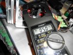
I was playing with the laser this afternoon and decide to add an ammeter (multimeter) between the driver and the diode.
Lab supply was set @ 8.0V and deliverd 2.4-2.5A (I set voltage, current is left unlimited.)
Surprisingly the multimeter reads 3.6xx mA to the laser diode.
I don't know why that is. I'm not acusing anyone, maybe I touched the potmeter with my fingers when handling it.
I soon realized that increasing temperature on the driver gives a higher amperage to the laser.
With a little screwdriver I set the driver @ 4.1xx mA (and I realized how sensitive that potmeter is)
Amperage quickly ramps up. After ~5 minutes the driver delivers 4.620mA and the 445gram module is 51degree Celsius (123.8 degrees Fahrenheit). Measured with IR-thermometer gun pointed close to a piece of black tape that I added to the heatsink. Room temperature is 26 degree Celsius (78.8 degrees Fahrenheit, yes its a nice summer :))
Lab supply was of course still set @ 8.0V and delivered 3.0 Amps in the end

I disconnect power.
And reconnect after 1 minute with the heatsink still quite warm and driver having the same temperature as the heatsink now.

It takes 1-2 minutes for the driver to start from 4.1xx mA and ramp up to +46xx mA.
Kind of a heat-sensitive driver, right?
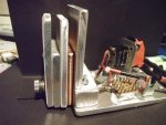
I hope it's not that little aluminium holder that is causing it.
I will make one out of plastic tonight.

Any thoughts?

I use an inductive amp meter, putting your meter in line will introduce resistance, using smaller wire will introduce resistance, and apparently getting even non ferrous metal near the inductor can affect these buck/boost type drivers.
I saw a difference in output when I first used solid core wire to attach the driver because the holes are smaller on these 4-6 amp drivers than the 2.4 amp drivers. You need to use heavy gauge wire such as the silicon wire that comes with it and keep both sides the same length and as short as possible.
My driver was set at 5 amps and I thought it was 4.5 until I balanced my wire and used the heavy gauge. My inductor is covered in aluminum but my driver works perfectly. My culprit was the wire. But I recommend going with the experts and not putting any metal near your inductor.
p.s. I have 2 of these NUBM44 diodes 1 in this test bed for working with optics that have yet to be delivered and the other in my finned flashlight, but I did check my other driver and it was set at 4.5, this one was set at 5.0 DTR is really good about doing a good job so it's probably your meter being in the circuit.
 

Attachments

  • SANY0215.JPG
    SANY0215.JPG
    210.2 KB · Views: 188
  • SANY0144.JPG
    SANY0144.JPG
    100.2 KB · Views: 378
Last edited:


Joined
Sep 12, 2007
Messages
9,399
Points
113
Firstly, it's silicone. Silicon is a shiny, brittle metal.

Secondly, isn't that popular silicone-insulated wire 24awg? No one outside of LPF would consider 24awg "heavy", and especially not for 5 amps.

Thirdly, are you using a constant current driver or not?

Finally, your "keep both sides the same length" advice is total bullshit. Knock it off.
 
Joined
Jul 10, 2015
Messages
9,900
Points
113
Firstly, it's silicone. Silicon is a shiny, brittle metal.

Secondly, isn't that popular silicone-insulated wire 24awg? No one outside of LPF would consider 24awg "heavy", and especially not for 5 amps.

Thirdly, are you using a constant current driver or not?

Finally, your "keep both sides the same length" advice is total bullshit. Knock it off.

Hey fella, I am not trying to be a smart ass. I think some things get lost when in text. I said experts giving you guys credit, not being rude.
I am using the same driver that DTR sends out with all these NUBM44 diodes and the silicone wire is heaver than the solid copper wire I threaded through the driver holes and it made a difference.
 
Joined
Jun 26, 2015
Messages
31
Points
8
I soldered approx 10-15cm 20AWG soft silicone wire into 4mm gold plated banana's for this test. The 4mm's fit in the multimeter. The other end has 2mm gold plated banana's that I can connect between the diode and driver.

I already added the 2mm banana's between driver and diode when I installed both into the heatsink like three days ago. It was just to extend the wire a little bit because it was a few mm's short. But I did not take that little effort to actually measure current. Not until today

Usually I use 12AWG soft silicone wire in 4mm banana's for my lab supply and/or multimeter to keep resistance to a minium. I have made various lenghts in red en black for easy use. But because it is very hard (impossible without removing copper strings) to solder 12AWG into a 2mm banana, I used 20AWG. I have no other AWG values in between. At least not that soft flexible silicone.
 
Last edited:
Joined
Jul 10, 2015
Messages
9,900
Points
113
I soldered approx 10-15cm 20AWG soft silicone wire into 4mm gold plated banana's for this test. The 4mm's fit in the multimeter. The other end has 2mm gold plated banana's that I can connect between the diode and driver.

I already added the 2mm banana's between driver and diode when I installed both in the heatsink like three days ago. It was just to extend the wire a little bit because it was a few mm's short. But I did not take that little effort to actually measure current. I did that today

Usually I use 12AWG soft silicone wire in 4mm banana's for lab supply and/or multimeter. I have made various lenghts in red en black for easy use.

I just wanted to let you know that when I mixed in some smaller solid core wire that it made a difference in my drivers output. Someone else had said to keep the wires as short as possible with these higher current drivers/diodes.
 
Joined
Jun 26, 2015
Messages
31
Points
8
I just wanted to let you know that when I mixed in some smaller solid core wire that it made a difference in my drivers output. Someone else had said to keep the wires as short as possible with these higher current drivers/diodes.

Thank you :)
Everyone's help is very welcome and much appreciated

And I wanted to let you guys know how I actually tested it. So there it is in my previous posts.
But I still would like to know what is wrong with my driver or where I f*cked up
 
Last edited:
Joined
Sep 12, 2007
Messages
9,399
Points
113
Fun fact: Paying extra for silicone insulation makes ZERO difference in the electrical properties of the wire (at DC). It simply makes it slightly more flexible. Strand count also has an effect on flexibility.

I am using the same driver that DTR sends out with all these NUBM44 diodes and the silicone wire is heaver than the solid copper wire I threaded through the driver holes and it made a difference.

Either your measurement technique is flawed, or you're accusing DTR of selling shitty drivers. My money is on the former.

A constant current driver doesn't give two shits about the wire gauge.
 
Joined
Jul 10, 2015
Messages
9,900
Points
113
Fun fact: Paying extra for silicone insulation makes ZERO difference in the electrical properties of the wire (at DC). It simply makes it slightly more flexible. Strand count also has an effect on flexibility.


Either your measurement technique is flawed, or you're accusing DTR of selling shitty drivers. My money is on the former.

A constant current driver doesn't give two shits about the wire gauge.

Well, get this much straight: I am not accusing DTR of anything, I have been 100% satisfied in all my dealings with him over the years.
I also used the thin solid core wire on the output side of the driver if that makes any difference. My reading with the thin wire was 4.5 A to the diode, after switching it out for the thicker wire it was 5.0A...my meter battery is good....maybe I bumped the zero or something, but I'm most certainly not accusing anyone of anything.
p.s. Both my NUBM44 diodes and the drivers are working great.
 
Last edited:
Joined
Jun 26, 2015
Messages
31
Points
8
Fun fact: Paying extra for silicone insulation makes ZERO difference in the electrical properties of the wire (at DC). It simply makes it slightly more flexible. Strand count also has an effect on flexibility.

True, I know :)
But the way you say it makes it look to me like you are saying it is not worth the money.
I don't use many meters of it, I think it is worth that little extra money.

It has the right colours (red and black.) In local hardware stores here in Holland, most of their wires are solid cores or at least much thicker strands which makes it less flexible and have different colours like house electrical wire you put in walls. (I don't know how you call those types of wires in English)
The other choice is 2-pole (3 with earth grounding) electronic device/machine cable. That's pretty much all they sell here.

Where silicone insulation doesn't shrink/burn away when putting it inside a solder pot or holding against a solder iron. Unlike that common (PVC?) insulation.
And it is pre-tinned.
And basically its the flexibility I like. :)
But the reason why I so explicitly called it 20AWG soft silicon wire is because I don't think my wiring has anything to do with it.
But my wiring was questioned.
Now you guys can have an idea what kind of wires/materials/method I used or else I was afraid for comments like these:
-How you know your wire is 20AWG? You are assuming that?
-What kind of quality banana's do you use?
-aligator clips can be a problem when they don't clamp well, did you use those?
-etc.


I really like to solve my problem or what I did wrong
Please, no hard feelings towards each other :)
All help is wanted
 
Last edited:
Joined
Jul 10, 2015
Messages
9,900
Points
113
True, I know :)
But the way you say it makes it look to me like you are saying it is not worth the money.
I don't use many meters of it, I think it is worth that little extra money.

It has the right colours (red and black.) In local hardware stores here in Holland, most of their wires are solid cores or at least much thicker strands which makes it less flexible and have different colours like house electrical wire. (I don't know how you call those types of wires in English)

It's insulation doesn't shrink away when putting inside a solder pot or against a solder iron. Unlike that common (PVC?) insulation.

And basically its the flexibility I like. :)
But the reason why I so explicitly called it 20AWG soft silicon wire is because I don't think my wiring has anything to do with it.
Now you guys can have an idea what kind of wires I use or else I was afraid for comments like:
-How you know your wire is 20AWG?
-What kind of quality banana's do you use?
-aligator clips can be a problem when they don't clamp well, did you use those?
-etc.

Yea I'm not sure why you are having a problem, how is your output without your meter in the loop?
Just to be clear the solid core wire I used was way too thin, but it still only caused a .5 Amp drop by my measurement.
Do you still have that aluminum strap across your inductor? If so you should remove it.
 
Last edited:
Joined
Jun 26, 2015
Messages
31
Points
8
I replaced the aluminium with plastic.
Unfortunately the problem is not solved. Only got bigger

It started again @ 4.1xx mA and it goes up from there. along with the temperature. Much faster than with the aluminium holder.
I measured at least 74 degree Celsius (165.2 degrees Fahrenheit) on the plastic with IR thermometer gun. But the driver with the plastic is probably to small for the sensor, so real temp must be higher I think.
Suddenly it peaked little over 5000mA and I disconnected power.
The plastic has become soft from the heat and the driver came loose from the heatsink.

I applied Artic Silver 5 only on the 8pin chip.(as recommended)
Only the 8pin chip is touching the heatsink (it is the highest chip or component on that side of the driver)

That pocket I machined on the mill has an almost mirror finished smooth underground.
Thermal conductivity should be no problem.
Other people with SXD drivers, how hot is you driver and how do you guys heatsink it?

Or maybe DTR or Lazeerer have some advise for me?
 
Last edited:
Joined
Jul 19, 2015
Messages
3
Points
0
Just used the NUBM44 + XYZ block (w/SXD driver) that I purchased from DTR for an engraver I'm making, and have run in to some trouble. I emailed DTR, but maybe the forum can give a faster response...

This is what I did:

Hooked it up to a 12V power supply,
Turned it on for a second or so, (everything was good and bright)
Turned it off for a few minutes,
Turned it on for 3 or 4 seconds, (everything was good and bright again)
Turned it off again...

And after that it, is not turning on again. I have checked the connection between the power supply and the driver with a multimeter and it is getting power. It seems like something died, in the diode or the driver. Maybe an internal short, static shock, or something thermal. I did not adjust the current limiting pot before turning on - it arrived turned clockwise about 3/4 of the way through its rotation. Reading through these forums, it seems like that should have put the diode in a decent current range of 4-5A.

I metered the wires coming out of the driver to the diode and there is no voltage there. I'm not sure if this is because the driver failed, or because the diode failed and then the driver subsequently failed because it was operated without a load.


Any ideas about what might have been wrong, or what I wrecked?
 
Last edited:
Joined
Jun 26, 2015
Messages
31
Points
8
Yea I'm not sure why you are having a problem, how is your output without your meter in the loop?
Just to be clear the solid core wire I used was way too thin, but it still only caused a .5 Amp drop by my measurement.
Do you still have that aluminum strap across your inductor? If so you should remove it.

I can not say anything useful about output without the ammeter. Either way it is bright as hell. what I do know is that the heat problem also occurs without ammeter.

I think the issue is heat.
Here is a crazy thought:
Is it possible that the heat from the driver is lowering the resistance in the potmeter? because the variable resistor in the potentiometer is made out of graphite. And graphite conducts electricity better when it gets hot.
I do know that the potentiometer on the driver is very sensitive when it comes to adjusting. What do you guys think?

But where does the heat come from? or is it that simple that the driver is not heatsinked very well and just heats up the hole driver? That the only contact between the 8pin and heatsink is just not enough?

Yes the hole 8-pin chip surface area is touching the heatsink. it is mounted nice and flat.

The reason I didn't fill the hole thing up with Artic Silver 5 is because if that is not the problem, then I have a driver completely covered with that crap for no reason.
I also don't have much left and even the smallest syringe is pretty expensive here.
 
Last edited:
Joined
Jan 8, 2009
Messages
3,145
Points
83
@ 5A that driver os going to get very warm I would suggest arctic thermal adhesive to the sink. If I read right your reading the current going to the driver from the power source, what you need to know is how much current is going to the diode. Having a testload capable of this is a challenge, at least to me, now assuming you did not originally move the pot, but posting you did, who knows now what your output is. Sounds like your basing this off your experience with linear drivers.
 
Joined
Jan 8, 2009
Messages
3,145
Points
83
Just used the NUBM44 + XYZ block (w/SXD driver) that I purchased from DTR for an engraver I'm making, and have run in to some trouble. I emailed DTR, but maybe the forum can give a faster response...

This is what I did:

Hooked it up to a 12V power supply,
Turned it on for a second or so, (everything was good and bright)
Turned it off for a few minutes,
Turned it on for 3 or 4 seconds, (everything was good and bright again)
Turned it off again...

And after that it, is not turning on again. I have checked the connection between the power supply and the driver with a multimeter and it is getting power. It seems like something died, in the diode or the driver. Maybe an internal short, static shock, or something thermal. I did not adjust the current limiting pot before turning on - it arrived turned clockwise about 3/4 of the way through its rotation. Reading through these forums, it seems like that should have put the diode in a decent current range of 4-5A.

I metered the wires coming out of the driver to the diode and there is no voltage there. I'm not sure if this is because the driver failed, or because the diode failed and then the driver subsequently failed because it was operated without a load.


Any ideas about what might have been wrong, or what I wrecked?

Try putting a load on it and measuring the current.
 
Joined
Jun 26, 2015
Messages
31
Points
8
@ 5A that driver os going to get very warm I would suggest arctic thermal adhesive to the sink. If I read right your reading the current going to the driver from the power source, what you need to know is how much current is going to the diode. Having a testload capable of this is a challenge, at least to me, now assuming you did not originally move the pot, but posting you did, who knows now what your output is. Sounds like your basing this off your experience with linear drivers.

Both.

There is an ammeter build-in the lab supply.
And there is an ammeter (multimeter) between driver and diode.

The lab supply is powering the driver, the driver is powering the laser diode.
I know I have written a lot. But all info in on the last three pages
 
Last edited:


Top