Welcome to Laser Pointer Forums - discuss green laser pointers, blue laser pointers, and all types of lasers

LPF Donation via Stripe | LPF Donation - Other Methods

Links below open in new window

ArcticMyst Security by Avery

NUBM44 6W+ 450nm Laser Diode

Joined
Jun 24, 2010
Messages
159
Points
0
As I posted above, I believe my meter is pretty close to DTR's. I compared a P73 and a 3W, 9mm diode against his runs of these diodes, posted on his site. My measurements were 10% and 5% lower respectively and that could certainly be partly a diode to diode variation as well as some variation in the meters. CD got almost identical power output/A as I did, but he was able to run his diode up a little higher. My optics free max was 5.6W @4.4A. Even a NIST certified, calibrated power meter will not produce a final benchmark unless 5-10 diodes are tested. These are harvested and the series is evolving rapidly. They may vary significantly.

Now, I am waiting to here what CD's beam manipulation produces, but what about everyone else with one of these diodes? Is the beam as big and divergent as mine (I suspect a defective diode)? Can a lens pair, placed very close to the collimator, better counter the divergence? Do prisms actually work better here than they do on other diodes?


DTR

0
Joined
Jun 24, 2010
Messages
5,684
Points
113
Below is a new one I set up a few hours ago and sent to Planters today which he should have by Saturday. He is also sending me the one he has to test so we can compare notes. I sent him it with the large sink and lens to rule out those small mounts causing more heat build up or the G-9 lens not cleaning up well or just low pass as I have seen a few that did not perform well. Anyway all the ones I have tested have been 6.4W @ 4.5A +/- 300mW. Planters is seeing 5.6W there which is pretty low so I look forward to testing that one and seeing what he gets with this one.

My meeter was tested by Lazeerer a few weeks ago and he measured it within 15mW of his @ 6W which with the fluctuations while running higher power diodes that is about as close to equal as you can get so unless both of ours are out of spec it should be on target.

These diodes do require very good heat management. The lower the ability to draw heat away from the base of the diode the lower the current the diode will fold back.

 
Joined
Jun 24, 2010
Messages
159
Points
0
This is a very good idea (DTR's). Although, I'll bet my heat management is at least as good. Testing the diode as he has set it up followed by placing it in my set up will help to reduce some uncertainty here.

In the mean time let's see some beams!
 
Joined
May 16, 2015
Messages
350
Points
0
Indeed, a great idea, and I(and I'm sure I speak for most everyone here on LPF) really appreciate the work you guys do and the fact that you put it out here for everyone to see. It's quite apparent why the diy laser scene has grown so immensely over the past few years. Thanks to both of you. And all the others who put so much into this community as well. I look forward to seeing how the swaps measure. It is starting to look like maybe Planters' diode might just be a runt. Lol. But we will know for sure soon!

@noobphaser215 Hope I didn't come off as being a smart-ass. I was just trying to say that we have several measurements now, and I think most of them seem to support it being a 6 to 6.5 watt diode, possibly maxing as high as 7+ watts, though we won't be absolutely, 100% 'for sure' until we have more data. But now that DTR has built more and verified that his LPM is accurate, I feel pretty confident in it.
 
Last edited:
Joined
Feb 25, 2010
Messages
1,643
Points
113
As I posted above, I believe my meter is pretty close to DTR's. I compared a P73 and a 3W, 9mm diode against his runs of these diodes, posted on his site. My measurements were 10% and 5% lower respectively and that could certainly be partly a diode to diode variation as well as some variation in the meters. CD got almost identical power output/A as I did, but he was able to run his diode up a little higher. My optics free max was 5.6W @4.4A. Even a NIST certified, calibrated power meter will not produce a final benchmark unless 5-10 diodes are tested. These are harvested and the series is evolving rapidly. They may vary significantly.

Now, I am waiting to here what CD's beam manipulation produces, but what about everyone else with one of these diodes? Is the beam as big and divergent as mine (I suspect a defective diode)? Can a lens pair, placed very close to the collimator, better counter the divergence? Do prisms actually work better here than they do on other diodes?

Warning....LONG WINDED READ...grab a beer !!!:drool::drool::drool:

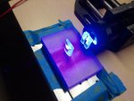
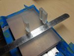
OK....did some quick and dirty tests.....see the pics !!! I placed a set of 6X Cylindrical optics...very, very close to the output of the G2 lens...maybe 2mm distance.

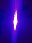
The farfield measurement was approx. 11mm wide by 10mm tall at a farfield target distance of 25' (7.6M). We need to do some masking for there are vertical wings presented when using the CL pair !!

The cylindrical to cylindrical inside plane to plane separation is 28.57mm.
I favor the Cylindrical set correction for it will cause less optical loss than the Anamorphic prism pair set up.

I will measure the farfield again....using the Anamorphic pair. I was in a big hurry when I got a 9mm wide farfield ???

This was a crude set up....but....it is a start in determining if this diode can be tamed !!! At least for use in the HH format....as for Projector use ??? Hmmm??

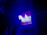
I measured the nearfield with the above Cylindrical set up... Yikes !!!
The beam presents at about 6.5mm wide....which is linked to the small distance from the first C-lens to the LD output !!!

There exists an inverse relationship !!!=====>

The closer the cylindrical lens set is located next to the LD....the larger the nearfield geometry is and the smaller the farfiels divergence is...So...for the HH application....who cares what is going on at the nearfield !!! It does not matter !!!!!

BUT...for projector use....we do care !!! a lot.... For our beam must " fit " on the scanner mirrors....and if it is too big....then....we waste precious photons...that fail to strike the scanner mirrors....and slip past on either side !!!

Well....then....you would likely say...." Hey...just use bigger scanner mirrors "
Well...yes....that would make sense !!! BUT....the bigger the mirror....the more inertia is introduced into moving the mirrors....
You must remember...scanner mirrors ...move back and forth....30,000 to 40,000 TIMES............PER SECOND....When you look at them....they are just a blur !!!!!

SO...that is what we are up against....and that is why scanner mirrors are kept as small as possible.....SO....the projector group must be concerned with both the Near field...and Far field beam geometry !!!!

The take away is that this diode will likely not be incorporated into laser projector use....IMNSHO !!! hahaha....

Anyway....it is a start !!! For the HH ( Hand Held). format...this diode can be tamed !!....:drool::drool::drool::drool:

Might I suggest an Aluminum heat sink....with a front semi-circle extension.....and on that extension....two (2) Cylindrical lenses could be epoxy set...at the optimal distance....and a spatial filter (mask) also be placed at the very end to eliminate the vertical wings !!!....just a thought.....search " EZ adaptor " for a visualization !!!...and see the pics I just added below !!!

The final take-away....the beam from this diode is gonna take some..." hammering " to make it presentable ...NOT PERFECT....but....presentable....for my tastes !!!
 

Attachments

  • OE1.jpg
    OE1.jpg
    169.3 KB · Views: 1,133
  • OE2.jpg
    OE2.jpg
    185.1 KB · Views: 311
  • OE3.jpg
    OE3.jpg
    107.3 KB · Views: 316
  • OE4.jpg
    OE4.jpg
    56.8 KB · Views: 418
  • EZCA-CL-V11.JPG
    EZCA-CL-V11.JPG
    161.7 KB · Views: 421
  • 3 EZ sans prism and collimation lens.JPG
    3 EZ sans prism and collimation lens.JPG
    94.2 KB · Views: 370
Last edited:

APEX1

0
Joined
Mar 17, 2015
Messages
1,084
Points
63
@noobphaser215 Hope I didn't come off as being a smart-ass. I was just trying to say that we have several measurements now, and I think most of them seem to support it being a 6 to 6.5 watt diode, possibly maxing as high as 7+ watts, though we won't be absolutely, 100% 'for sure' until we have more data. But now that DTR has built more and verified that his LPM is accurate, I feel pretty confident in it.

not at all bud.. :) the video Jordan posted is the answer I was looking for:beer:
I'll be picking one of these up soon. Definitely going with an all copper host. I cant wait to see when people start posting there builds with this bad boy in it :drool:
 
Last edited:
Joined
Feb 25, 2010
Messages
1,643
Points
113
OK.....did a few more measurements......Here is the deal....the Anamorphics are NOT the way to go.....I could get no less than 15mm divergence at the Far field using the G2 lens !!!

When I first tested the Anamorphics....I was using the O-Like glass lens....well....that lens sucks....as it lowers the raw power to about 4W....screw that !!! So....as far as I am concerned....the G2 is the best lens....as of 7.9.2015 !!! Maybe somebody else will find a better collimation lens......but....for me....for now....the lens of choice is the G2 !!!

Went back and really fine tuned the Cylindrical lens to lens distance !!!
This distance is critical to achieve the minimal divergence....and just a .1mm movement will cause a change in the Far field divergence !!!!!

Well...the new minimal Farfield geometry/width is about 10.76mm ...with a beam thickness of 9.5 mm !!! And...that ain't bad !!! But not as good as we have been able to tame the P-73 !!! Note: this measurement was taken at 25' ( 6.7M )

See pics below....OE5 is the improved positioning of the Cylindrical lenses and OE6 shown the Anamorphic Prism set....doing what it can !!! Lame !!
 

Attachments

  • OE5.jpg
    OE5.jpg
    139.7 KB · Views: 545
  • OE6.jpg
    OE6.jpg
    142.1 KB · Views: 246
Last edited:
Joined
May 1, 2011
Messages
949
Points
0
Thank you CDbeam for your contribution towards the correction of this diode. I knew the prisms weren't going to cut it. What magnification are you using for your corrective lenses? If they're 4x then would 6x be better? Could that be the key to better correction?
 
Joined
Jul 4, 2012
Messages
2,834
Points
63
This is a very good idea (DTR's). Although, I'll bet my heat management is at least as good.

Understatement, to say the last. I really think you just got a dud diode. Maybe an oddball that isn't up to spec, who knows. But I don't think the heat has anything to do with it (in your case), it's certain the input is fine, and the measuring devices are fine, so that leaves the diode- my bet is the new diode you get will be on par with everyone elses findings :)
 
Joined
Jul 10, 2015
Messages
9,907
Points
113
I hate to be the bearer of bad news, but my brand new NUBM44 that I got from DTR a week ago just went bubble in the middle of the bar. I have it in a heavy test bed and only run it a minute at a time never getting it but slightly warm and today I turn it on and it wont focus, then I take out the lens and the bar has that same rupture bubble. The diode window is clear. My batteries are 2 fully charged NCR18650's and I had DTR set the driver at 5A, maybe these just cant stand that much current?
 

Attachments

  • SANY0088.JPG
    SANY0088.JPG
    188.5 KB · Views: 407
  • SANY0095.JPG
    SANY0095.JPG
    194.2 KB · Views: 378
  • SANY0090.JPG
    SANY0090.JPG
    170.6 KB · Views: 445
Joined
Sep 8, 2014
Messages
124
Points
18
I hate to be the bearer of bad news, but my brand new NUBM44 that I got from DTR a week ago just went bubble in the middle of the bar. I have it in a heavy test bed and only run it a minute at a time never getting it but slightly warm and today I turn it on and it wont focus, then I take out the lens and the bar has that same rupture bubble. The diode window is clear. My batteries are 2 fully charged NCR18650's and I had DTR set the driver at 5A, maybe these just cant stand that much current?

I can see the mark on the diode window of your picture. It looks to be right where that bubble in your raw output is. But in that picture there most definitely looks like some thing on the middle of the diodes window.

And I am not to sure that your heatsink would have been efficient enough to have run this diode @5amps for 1 minute at a time.
 
Last edited:

DTR

0
Joined
Jun 24, 2010
Messages
5,684
Points
113
I hate to be the bearer of bad news, but my brand new NUBM44 that I got from DTR a week ago just went bubble in the middle of the bar. I have it in a heavy test bed and only run it a minute at a time never getting it but slightly warm and today I turn it on and it wont focus, then I take out the lens and the bar has that same rupture bubble. The diode window is clear. My batteries are 2 fully charged NCR18650's and I had DTR set the driver at 5A, maybe these just cant stand that much current?

Yea while we certainly don't know about currents 5A and above that looks like an obstruction to the light. The halo effect I was mentioning before. If there was damage to the diode itself the edges would not still have the bar shape and the total output would look more rounded. If you want send it over and let me decan it for you it should come back to life.;)
 
Joined
Jul 10, 2015
Messages
9,907
Points
113
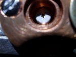
Yes I just looked at it with a jewelers loop and it has a burn in the diode window. I have a dozen working 445's from a140 through 7875's and they are all clean. I don't let garbage get in and this diode was working like a champ until all of a sudden it goes bubble. I have not had the lens in and out except once when mounting it a week ago. OK I just took a good long look at the diode window and the halo burned onto it looks gold colored and the 3 element is lighter than some others. This may in fact be the anti reflective coating from the 3 element burning off. Is there a way I can clean it? If not I will gladly accept your generous offer to decan it for me. Thank you. BTW will oxygen degrade the gain medium? Ok 3rd edit here, I cleaned it with 91% isopropyl alcohol and a Q-tip and looked at again with the loop and it looks like a bubble inside the diode window. I will dig out my microscope camera and see if I can get a good close up.
 

Attachments

  • SANY0109.JPG
    SANY0109.JPG
    191.6 KB · Views: 293
  • SANY0113.JPG
    SANY0113.JPG
    173.3 KB · Views: 294
  • SANY0118.JPG
    SANY0118.JPG
    166 KB · Views: 267
Last edited:
Joined
Jan 8, 2009
Messages
3,145
Points
83
I'm wondering if the method of extracting these is leaving material on the windows... I checked up on mine after receiving it and there was quite a bit of fine particulates on the window. I now going to try some canned air to remove when I get a chance.
 

DTR

0
Joined
Jun 24, 2010
Messages
5,684
Points
113
I'm wondering if the method of extracting these is leaving material on the windows... I checked up on mine after receiving it and there was quite a bit of fine particulates on the window. I now going to try some canned air to remove when I get a chance.


Extraction method is pretty clean. There would not be any excess dust or other particles being created due to it over other methods used for other pulls like the M140. I just checked all the ones I have extracted here and they are all spotless under my microscope. I do also power every unit including bare diodes to make sure they don't have anything obstructing the light path. Are you seeing anything in the output when you power it just to lasing threshold. That is how you can check without running the risk of burning anything on it.

kr8Cwl.jpg
 
Last edited:
Joined
Jan 8, 2009
Messages
3,145
Points
83
I have not put power to it yet. I only used a jewelers glass to view it and she was pretty dirty enough to just blow some off and see a difference.


Top