Welcome to Laser Pointer Forums - discuss green laser pointers, blue laser pointers, and all types of lasers

LPF Donation via Stripe | LPF Donation - Other Methods

Links below open in new window

ArcticMyst Security by Avery

Glass lens? dimming LD?

icwiz

0
Joined
Mar 6, 2011
Messages
24
Points
0
Hello Everyone,

I have a little 445nm a140 LD in an aixiz housing with an acrylic lens. I have about 900milliamps goin to it.

I have seen posts where people say anything over 300mw Must have a glass lens. But I have not had serious issues with it.

I do feel that the quality of the beam is not as high, or its not as bright as it used to be. Is this due to the lens? Or did i damage the diode? (the little window in the LD looks clear)


Is there damage that is caused by the laser beam reflecting back off the lens and hitting the diode?

Thanks for your help :)

--ICWiz


Joined
May 25, 2010
Messages
3,655
Points
0
:eek: Double :eek:

If you are really running it at 900mA you have done some serious damage to the diode WIndow and Possibly the diode aswell .

Most likely smoke on the diode window from the lens melting.

What driver are you using and what is you battery type.?

Think about it this way at 900mA of 445nm it melts plastic almost instant when focus. What do you think its doing to your Acrylic lens when its siting mm from the diode. Its slowly melting it. Well maybe not slowly more like fast.

Iam guessing you are not truly running it at 900mA. If you where it would take <1min for the lens to start melting and the dot starts to deform when pointing it onto the wall.
 

icwiz

0
Joined
Mar 6, 2011
Messages
24
Points
0
Merged multiple consecutive posts

See thats the werid thing. Ive only turned it on at the most, for about 30 seconds. The lens has gotten "warm", but it has never gotten hot. There is also no smoke or burning anything from inside the housing. The dot on the wall appears to be properly focused. The plastic lens appears to still be crystal clear.

Wait wait wait..i just realized that ive been measuring the amps at the wrong point in the circuit. Ive been measureing it at the battery to the driver, not between the driver and the diode. I'll check it again later.

The other reason I haven't done any extensive tests is because i didnt have goggles. I couldnt do more then shine a dot on a white wall in a sunlit room, or at the sky. My dragonlaser goggles just came in today :D

My glass lens should come in tomorrow.

I looked really close at the diode window under 10x magnification. I can make out the AR coating on the window, and it all appears to be clear. No deposits.

Thank a lot for your input lazeerer :D

Oh, I am using a lm317t with a 2 or 1 ohm resistor (when i tested it it wasnt exactly 1ohm) with a 9v battery.
 
Last edited by a moderator:
Joined
May 25, 2010
Messages
3,655
Points
0
Well thats you problem right there you are not running it at 900mA with a 9V battery.

1 ohm will give you 1.25A
2 ohm will give you 625mA


A 9V batter cannot supply enough to power this.

I Kinda figured thats what you were using.

You might be getting ~300mW or less.

This is why its not melting.

Iam not exactly sure exactly how much its putting out but i sure know its No were near what it should be putting out.

You Need to get 2x Lithium cells 3.6V each and when fully charged you should get 8.4V. 18650 would be best.
 
Last edited:
Joined
May 25, 2010
Messages
3,655
Points
0
You dint test load your set up before Hooking up the diode..?

Do you have a testload.?

:thinking:
 

icwiz

0
Joined
Mar 6, 2011
Messages
24
Points
0
Merged multiple consecutive posts

I made a testload out of a few diodes and a 1ohm resistor. But It never behaved just as the LD would. Plus I figured since the diode could handle all those miliamps, I could get away with just using a 1ohm resistor to regulate the voltage.

I have one of the next higher model of lm317 (i forgot the number) that can do 3A. I plan on actually making a proper housing and all that for this thing.

I guess i have to do more research on what the best battery for this type of setup is.
 
Last edited by a moderator:
Joined
May 25, 2010
Messages
3,655
Points
0
A test load its not just meant to test the currant. It also is used to make sure your circuit is working Fine.

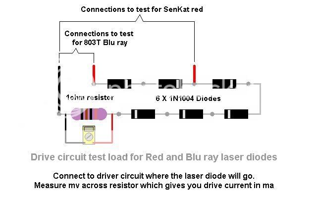
You need to use 4X 1NXXXX diodes and a 1ohm resistor for a test load for 445nm.

If you did make one properly you would know that it was not suppling enough power to Drive your driver and LD.

Not sure what Else to tell you but Get some Lithium cells as i suggested above. Build a proper testload and test your circuit to see what your driver is Suppling.

Also Stop using the Acrylic lens.
 

icwiz

0
Joined
Mar 6, 2011
Messages
24
Points
0
Merged multiple consecutive posts

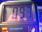
ok so i took a multimeter reading again and it shows .9 when i have the meter set to the 10amp setting. I figure that means 900ma. Am I reading this wrong? :eek:

i put the meter between the driver and the diode this time

Ok, so i had a makeshift battery pack made of 4 9v batteries in series (so the same voltage, but more juice) and turned it on for a second, it all looks the same.

Is it possible i have a defective diode that just isnt that bright? Is that heard of?

yeah, something weird is happening. I now tried a plugin 9v adapter that pumps out 800ma, the meter say 1.1amps
 
Last edited by a moderator:
Joined
May 25, 2010
Messages
3,655
Points
0
You have it is the wrong setting.

You have to put it on the DC side into mV. (2000m)

DO not use the 10A setting.

Also you are measuring it wrong. You have to take the test across the resistor Like so:
test_load01.jpg


But using 4 diode instead of the Six you see in the picture.
 
Last edited:

icwiz

0
Joined
Mar 6, 2011
Messages
24
Points
0
very sorry, I meant 10Amps. There are 2 settings, one for DC and another for AC. I am using the DC side (the next smallest demoniation is 200m)

Currently im testing with the diode itself ( since its a working laser i dont have to worry about blowing the diode...right? )

How long does it take for the acrylic lens to start to melt? Maybe im just not using it for long enough at a time and everything is actually fine?
 
Joined
May 25, 2010
Messages
3,655
Points
0
You need to use the 2000m. In order to read the currant in 1 increment. With a Proper TestLoad.

Iam telling you to use a testload. Like in the picture above. If you make one false move doing it the way you are or do something wrong you will be out 50$ rather then <10$ for the test load if it will even break the testload & to be Honest i have NO Idea what you are doing to test it.

Please post Pictures.


If you re read through my posts i said if its running at that high of a power it would only take seconds for it to melt.

DO you even know what resistor you are using.? You said its either 1ohm or 2ohm. witch one is it.?

Also You said you made a testload with a few diodes. That makes no sense. Please post a picture of this testload so i can see what you have made.

Either way you are not getting any of those powers with 1 9V cell.

I dont know what else to say to you.
 
Last edited:

icwiz

0
Joined
Mar 6, 2011
Messages
24
Points
0
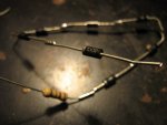
When i first created the circuit, i used a testload. It is 4 diodes and a 1ohm resistor. I basically followed that same pic you posted. I had found it while researching how to make this.

The reason I said that i was not sure if the resistor in the circuit may be a 1 or a 2 is because the color code says 1ohm, but when i measure it with a meter it comes out to 1.8ish.

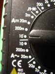
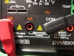
The meter does not have a 2000m. It goes from 200m to 10. (maybe i need to get just a amp meter with more sensitivity?)

even at the 10a setting, it can read to the hundredth. When measuring the current with the laser diode in operation, it comes out to 1A on a fresh 9v battery.

So is the meter wrong? if it says 1a, then is that not how much the circuit is providing?

Would you happen to know how much power in volts and amps im supposed to give the circuit in order to be able to push enough power through?

I attached pics of the meter, the testload and the output of the meter.

Thanks a lot for your input :)
 

Attachments

  • IMG_3301-.JPG
    IMG_3301-.JPG
    104.5 KB · Views: 84
  • IMG_3302-.JPG
    IMG_3302-.JPG
    87.6 KB · Views: 84
  • IMG_3303-.JPG
    IMG_3303-.JPG
    175.6 KB · Views: 78
  • IMG_3304-.JPG
    IMG_3304-.JPG
    154.5 KB · Views: 74
Joined
Jul 17, 2010
Messages
2,160
Points
0
Don't ever measure between the diode and driver!!! You can easily kill your diode. You measure across the resistor in your test load in mv not ma, and with a 1 ohm resistor 1mv=1ma. Hope this helps.
 

icwiz

0
Joined
Mar 6, 2011
Messages
24
Points
0
Merged multiple consecutive posts

Don't ever measure between the diode and driver!!! You can easily kill your diode. You measure across the resistor in your test load in mv not ma, and with a 1 ohm resistor 1mv=1ma. Hope this helps.

Why would that kill the driver? Even with a test load you cant be 100% sure if the regulator is putting the right current for the diode. I mean, Im sure there is the ever present problem of getting a capacitor discharge when reconnecting the diode to the driver, but I watched out for that.

but Still...The meter shows .9 amps. thats 900 milliamps.

and why would i measure the circuits in volts to see current? Ive never heard that before.

wait wait, im sorry Coherent Light, you're right. it says that.


but why? why do you measure in mv? can you point me to a noob document or something on this idea?
 
Last edited by a moderator:
Joined
Jul 17, 2010
Messages
2,160
Points
0
A resistor drops voltage across it, so You measure the voltage it drops not the current. It just so happens that the voltage drop across 1 ohm resistor in the test load equals the current flowing through the circuit. That's very convenient for Us since We need the current, and the voltage to the diode is no biggie. You can use other values for the resistor it is not a 1 for 1, so You have to do a bit if math to correctly figure the current.

This is a simplified explanation, but I hope you get the jest of it.


Top