Welcome to Laser Pointer Forums - discuss green laser pointers, blue laser pointers, and all types of lasers

LPF Donation via Stripe | LPF Donation - Other Methods

Links below open in new window

ArcticMyst Security by Avery

DRIVER circuit, M140, 445nm

Joined
Jun 26, 2013
Messages
39
Points
8
Good day.

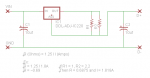
I hope this is not redundant but after much time browsing the forums and reading a lot of back and forth chatter on the topic I still have not found an actual built and known working diagram for a driver circuit using LM350. I want to drive M140 diode but do not need driver to be either tiny or to buck voltage.

This laser will be a lab laser, not portable, eventually in an engraver so being tiny is irrelevant and undesirable because it is harder to heat sink tiny :yh:

I plan to use a modified CPU power supply so I have option of 5V and 12V to work with so I can run fan and TE cooler from one source.

I have found the diagrams for LM317 which are essentially the same IC however most of those are configured for the red diodes.

SUGGESTION: Is there ( or can there be ) a section on this forum just for "stickies" of tested circuits for various diodes?

I hate re-inventing the wheel. If I don't find what I need I will build and test and post my final design.

Thanks and sorry if this was resolved in a simple post of circuit somewhere...but I could not find it. :D


benmwv

0
Joined
Sep 10, 2010
Messages
1,380
Points
48
This is the simplest way to make the circuit. It only needs two parts, the regulator and a resistor.

Resistor between adj and out. +12v to in. D+ to adj. D- to ground.

For the resistor value, R = 1.25 / I (where R is in ohms and I is in amps.

You will need some massive heatsinking though. Power dissipation (watts) in the resistor is 1.25 * I and power dissipation in the regulator will be around 6 * I.
 
Joined
Jun 26, 2013
Messages
39
Points
8
This is the simplest way to make the circuit. It only needs two parts, the regulator and a resistor.

Resistor between adj and out. +12v to in. D+ to adj. D- to ground.

For the resistor value, R = 1.25 / I (where R is in ohms and I is in amps.

You will need some massive heatsinking though. Power dissipation (watts) in the resistor is 1.25 * I and power dissipation in the regulator will be around 6 * I.

I have the schematic from the manufacturer but was looking for information where someone has done this and already calculated the values specific to driving the M450 diodes.

I am designing a PC board now.

Thanks much as your reply is always appreciated. :p
 

benmwv

0
Joined
Sep 10, 2010
Messages
1,380
Points
48
You using eagle? Ill make you a schematic file with the right part values real quick then you can change that over to a custom board.

If you are looking to run your diode around 1.8A (its m140 right?) You can use either a 0.68 resistor or a 1 and 2.2 in parallel.

Brb with some files ;)
 

benmwv

0
Joined
Sep 10, 2010
Messages
1,380
Points
48
Here you go sir :beer:

Just unzip that and put the whole folder in your eagle folder. Post back with your board when finished! And if you need any help just ask. Usually I increment the "v1" at the end any time I make a change (just always use save as instead of save), so I can always go back through all my files if I make a mistake somewhere.

I chose 1 watt sized resistors and a to-220 regulator. Also put in two 10uf capacitors. These aren't really required but they are recommended. Have fun!

Edit: Picture
attachment.php
 

Attachments

  • Simple Linear.zip
    16.4 KB · Views: 121
  • Linear.PNG
    Linear.PNG
    7.7 KB · Views: 3,214
Last edited:
Joined
Jun 26, 2013
Messages
39
Points
8
What seems strange between this and the suggested schematic from Fairchild's data sheet is that in theirs the output is not passing through the resistors.

Using LM350 as it is good to 3+ amps but otherwise same IC.

I prefer to not have 1.5 amps flowing through the resistors due to heat dissipation. :wave:

Here is link to data PDF. CLICK

Gotta take this up tomorrow...have a good evening.
 
Last edited:

benmwv

0
Joined
Sep 10, 2010
Messages
1,380
Points
48
No problem!

This design is all over the internet, all I've done is simplify it and make an eagle schematic ;) Use it however you want.

Awesome site! Quick note on your test load, you probably want to use the "red" on your test load if you are using high current as that setting will be around 5v load at 1.8A.
 

benmwv

0
Joined
Sep 10, 2010
Messages
1,380
Points
48
What seems strange between this and the suggested schematic from Fairchild's data sheet is that in theirs the output is not passing through the resistors.

Using LM350 as it is good to 3+ amps but otherwise same IC.

I prefer to not have 1.5 amps flowing through the resistors due to heat dissipation. :wave:

Here is link to data PDF. CLICK

Gotta take this up tomorrow...have a good evening.

To use the voltage regulator to regulate current the power must flow through the resistors. The voltage regulator adjusts the voltage at the output pin to keep 1.25v at the adj pin. So by using the voltage regulator to keep 1.25v over the resistors we are regulating the current flowing through the circuit using the formula I = 1.25 / R. That is why I used high power resistors in the eagle schematic. Inefficient I know, but since you are using a 12v supply It doesnt matter. This is the simplest way to make a good laser driver!
 

pow3r

0
Joined
May 19, 2013
Messages
17
Points
0
given the massive heat dissipation needs from the 12v input, why didn't you use the 5v from the PSU, wouldn't this require less energy to be wasted as heat?


Top