Asherz
0
- Joined
- Jan 18, 2009
- Messages
- 1,623
- Points
- 0
Hi guys,
I posted a thread a few days ago with a few pictures of my newely arrived host/diode and bits, and now have a some pics of it being put together + a build log, I decided to call it bullet, but originally I had planned it too look something a bit like a bullet
http://laserpointerforums.com/f65/new-package-56k-warning-62882.html#post896122 (original thread)
Anyhow, onto the pics, this build literally took me most of today after running into quite a few problems but in the end it's finally built. (2 diodes and a driver later.)
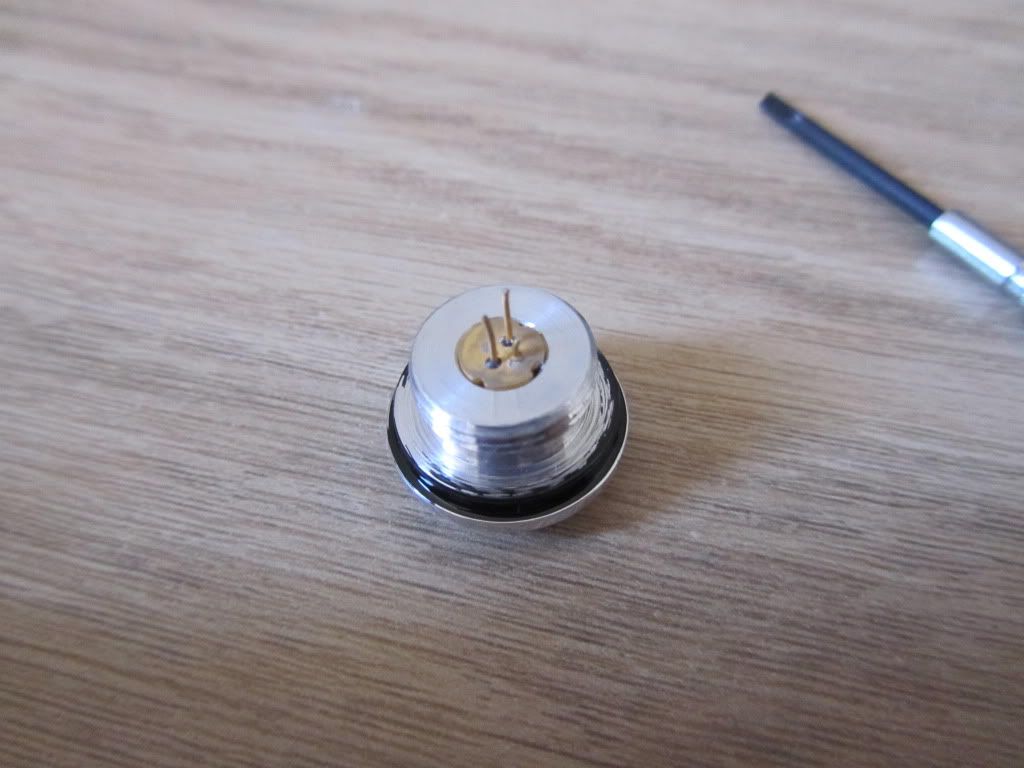
Diode pressed into the head of the host
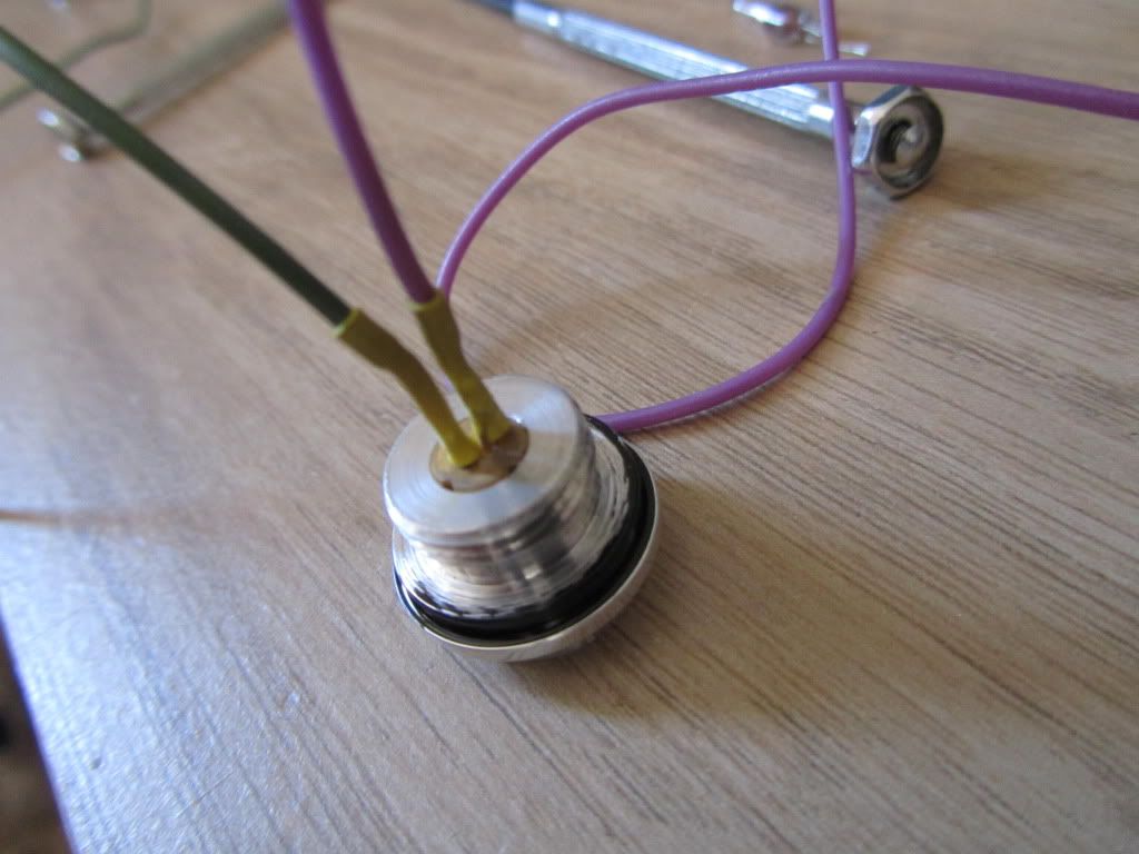
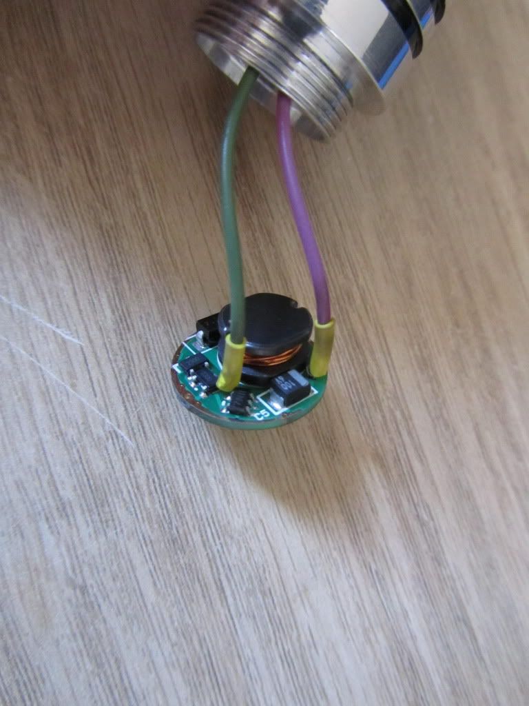
Wires soldered on, next to no heat applied, bother wires pre tinned and then just a quick tap of the soldering iron
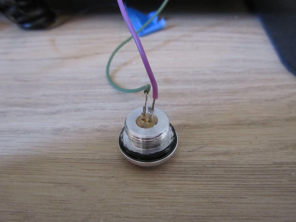
Heatshrink added onto the wires, to keep them from shorting
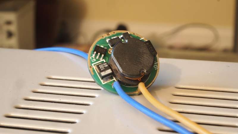
driver wired up, and then heatshrinked, positive input to the spring and negative to the host contact points around the edges.
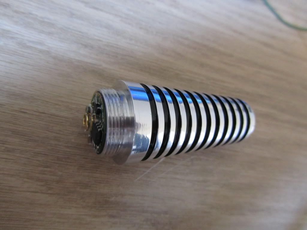
All closed up and completed
Unfortunatly, I got to this point, screwed the pill back into the host and put in a battery, and G*D D*MIT the diode had LED'd, how I'm not sure I think it was either very sensitive or a zombie because there was great care taken when setting up, I put it down to me not setting up the driver properly as my test load was a little stodgey.
This left me with a broken diode, and a driver I wasn't happy to use again, I wanted to get this build done today so I went to another build I had removed the aixiz module and spent a while trying to get the diode out WHICH I did eventually after lots of snipping, cutting and banging the diode and flex drive fell out. The can on the diode was damaged, this is where I decided to try decanning it and after careful use of a razor blade to my supprise it came off! I wasn't at this point expecting it to work thought but I carried on with the build.
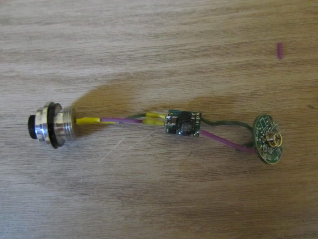
Too keep the clean look of the round driver in the pill end, I decided to strip one of the NJG-18 drivers of all it's componants and use it as a postive/negative input to the flex drive in the lower compartment of the host.
Carefully decanned diode:
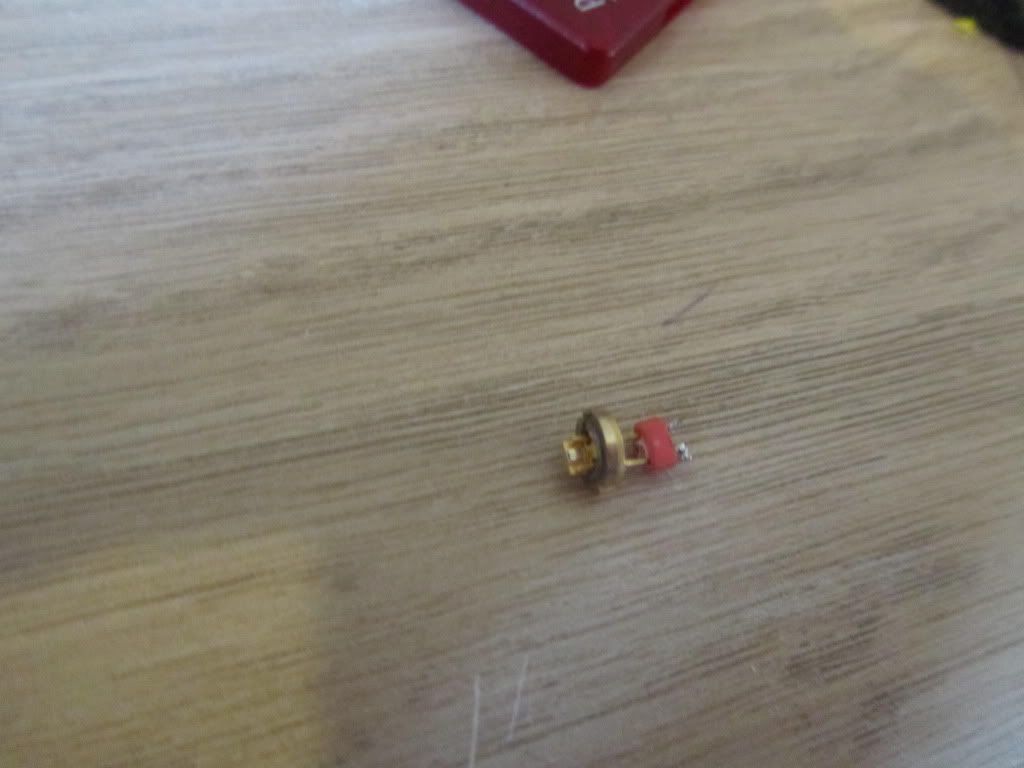
diode, flex drive then stripped NJG-18, this was then dissasembled and put into the pill with the flex drive/diode at the front part and NJG-18 at the back where it was previously to close the pill up.
And a quick teaser of her up and running! FINALLY!
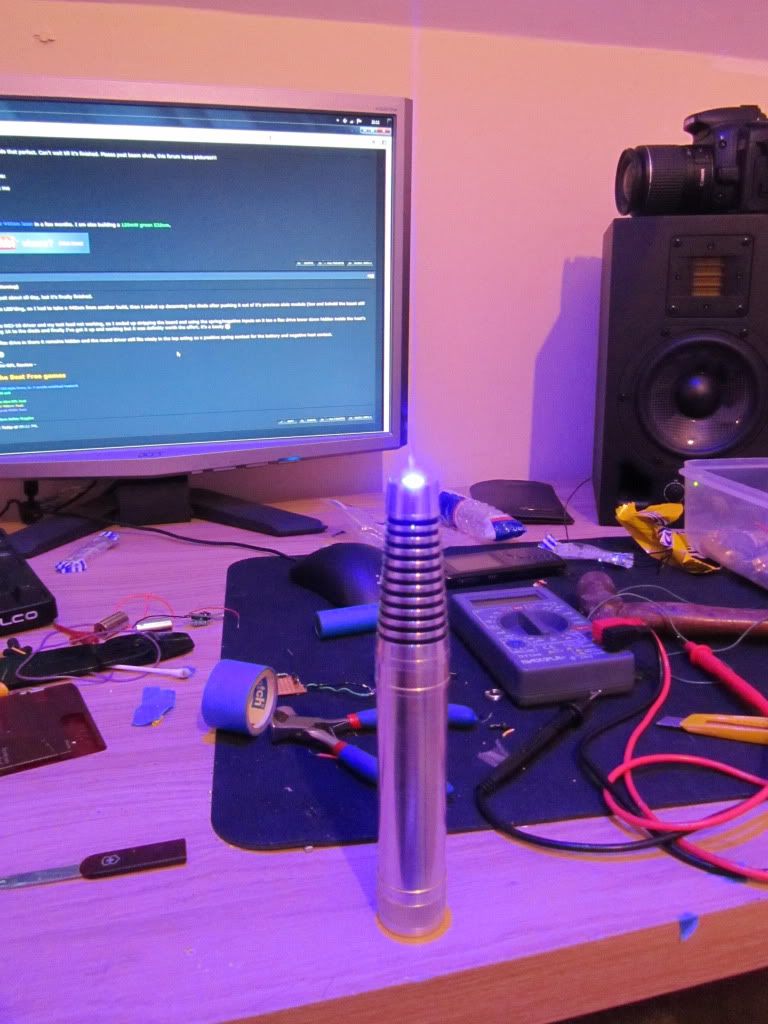
Burns through plastic like no tomorrow, more than enough power for me! I'll get some more beam shots and things later on and maybe a little video.
Please also note the focus ring that fits in with the host on the end, which works really well with the aixiz lens, which will need to be replaced with a more suitable 445nm lens to increase output power.
Well it was an expensive long build, but I think it's worth it for what is now a 445nm decanned build
I posted a thread a few days ago with a few pictures of my newely arrived host/diode and bits, and now have a some pics of it being put together + a build log, I decided to call it bullet, but originally I had planned it too look something a bit like a bullet
http://laserpointerforums.com/f65/new-package-56k-warning-62882.html#post896122 (original thread)
Anyhow, onto the pics, this build literally took me most of today after running into quite a few problems but in the end it's finally built. (2 diodes and a driver later.)
Diode pressed into the head of the host
Wires soldered on, next to no heat applied, bother wires pre tinned and then just a quick tap of the soldering iron
Heatshrink added onto the wires, to keep them from shorting
driver wired up, and then heatshrinked, positive input to the spring and negative to the host contact points around the edges.
All closed up and completed
Unfortunatly, I got to this point, screwed the pill back into the host and put in a battery, and G*D D*MIT the diode had LED'd, how I'm not sure I think it was either very sensitive or a zombie because there was great care taken when setting up, I put it down to me not setting up the driver properly as my test load was a little stodgey.
This left me with a broken diode, and a driver I wasn't happy to use again, I wanted to get this build done today so I went to another build I had removed the aixiz module and spent a while trying to get the diode out WHICH I did eventually after lots of snipping, cutting and banging the diode and flex drive fell out. The can on the diode was damaged, this is where I decided to try decanning it and after careful use of a razor blade to my supprise it came off! I wasn't at this point expecting it to work thought but I carried on with the build.
Too keep the clean look of the round driver in the pill end, I decided to strip one of the NJG-18 drivers of all it's componants and use it as a postive/negative input to the flex drive in the lower compartment of the host.
Carefully decanned diode:
diode, flex drive then stripped NJG-18, this was then dissasembled and put into the pill with the flex drive/diode at the front part and NJG-18 at the back where it was previously to close the pill up.
And a quick teaser of her up and running! FINALLY!
Burns through plastic like no tomorrow, more than enough power for me!
I'll get some more beam shots and things later on and maybe a little video.Please also note the focus ring that fits in with the host on the end, which works really well with the aixiz lens, which will need to be replaced with a more suitable 445nm lens to increase output power.
Well it was an expensive long build, but I think it's worth it for what is now a 445nm decanned build
Last edited: