Welcome to Laser Pointer Forums - discuss green laser pointers, blue laser pointers, and all types of lasers

LPF Donation via Stripe | LPF Donation - Other Methods

Links below open in new window

ArcticMyst Security by Avery

Another NES Zapper build, my first

Joined
Aug 2, 2013
Messages
10
Points
3
Hello LPF,

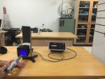
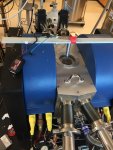
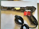
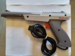
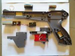
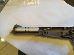
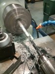
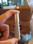
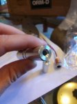
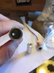
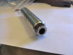
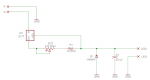
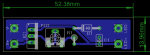
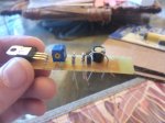
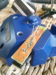
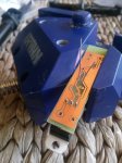
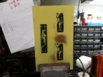
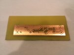
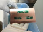
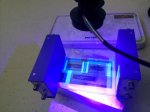
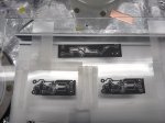
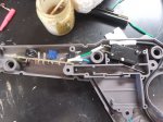
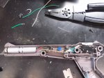
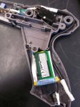
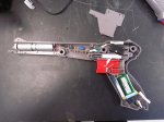
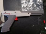
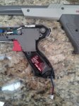
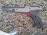
A couple of months ago I was reading through a favorite news site of mine and stumbled across North Street Labs and their modification of a 2W 445nm diode to an original NES Zapper. I thought it would be pretty cool, but thought it to be out of my scope. Well I found a Zapper gun at a flea market for 2 bucks and thought of it as a sign so here is my first electronics/laser build. In their build, they opted to use a 2.1A buck driver, but I wanted to try my hand at circuitry. So I went the easy route, and opted for a simple LM317 based driver. The circuit is based on Daedal's write-up. I chose this circuit due to its simplicity and size since the Zapper has roughly 60 x 16 x 16 mm of barrel space for the driver. I purchased the 445nm diode as a preassembled 12 mm module from DTR's laser shop, he sent it very quickly, and packaged very carefully with the leads shorted. I have attached some pictures of me taking the Zapper apart. In later posts I will be presenting some pictures of me fabricating the heatsink, my circuit schematic and PCB layout, my etching, soldering, dyeing, and silk screen process, and finally a post of it burning something, hopefully. Hope you guys enjoy. Please feel free to add any input; right now I'm trying to decide how to charge the batteries while in the circuit without opening the gun. Cheers!

Joe
 

Attachments

  • Inside1_s.jpg
    Inside1_s.jpg
    109 KB · Views: 3,373
  • Outside1_s.jpg
    Outside1_s.jpg
    94.1 KB · Views: 338
  • Fully gutted_s.jpg
    Fully gutted_s.jpg
    112.8 KB · Views: 585


Joined
Aug 2, 2013
Messages
10
Points
3
Hello again LPF,

I was able to get into the machine shop and make use of our lathe for fabricating the heatsink. I just found some scrap aluminum that was roughly 18 mm in diameter and decently long as my stock. Following along with NSL write-up I decided to leave the grooves in the zapper barrel so that the heatsink would seat itself and hopefully keep the beam in line with the zapper sights. I first had to turn the aluminum down from its original diameter to about 16 mm (in the end I found this to be a bit to small, and the heatsink is able to move slightly in the lateral direction. I used a vernier caliper to take measurements of the grooves needed to be cut in the heatsink. You can see in one of the images I made a goof on where to cut by forgetting to offset for the cutting tool, remember; measure twice cut once, I did it the reverse DOH!! The overall length of the heatsink is about 70 mm with one end bored and reamed to 12.5 mm and tapers down to ~3 mm at the first groove. Since heat dissipation is based on mass, leave as much in there as you can, this little diode gets hot! Since turning on a lathe creates sharp edges I beveled the ends and chamfered the wire feed through hole. Anyway enough chatter here are the pictures, hope you enjoy. Cheers!

Joe
 

Attachments

  • Heatsink_Seated_s.jpg
    Heatsink_Seated_s.jpg
    89.2 KB · Views: 652
  • Heatsink1_s.jpg
    Heatsink1_s.jpg
    77.8 KB · Views: 225
  • Heatsink2_s.jpg
    Heatsink2_s.jpg
    74.3 KB · Views: 199
  • Heatsink3_s.jpg
    Heatsink3_s.jpg
    94.3 KB · Views: 219
  • Heatsink_final1_s.jpg
    Heatsink_final1_s.jpg
    60.7 KB · Views: 234
  • Heatsink_final2_s.jpg
    Heatsink_final2_s.jpg
    56.1 KB · Views: 216
  • Heatsink_final3_s.jpg
    Heatsink_final3_s.jpg
    57 KB · Views: 228
  • Heatsink_withLED2_s.jpg
    Heatsink_withLED2_s.jpg
    75.7 KB · Views: 284
Joined
Aug 2, 2013
Messages
10
Points
3
Hello LPF,

Now that the heatsink is done, its time to figure out the circuitry for this laser. As I said my circuit is based on an LM317 voltage regulator. I have attached the schematic as well as an image of my PCB mockup. Once I have the board completed and am certain its working, I will post the eagle files for those who would like them. The design was done in EageCAD and made use of the gauss-markov library as well as the standard libraries. For now enjoy. Hopefully I will be etching this board on Saturday and soldering on Sunday. Cheers!

Joe

Edit: Added an earlier pcb mockup, changed it out for a smaller footprint potentiometer.
 

Attachments

  • LM317_Sch.png
    LM317_Sch.png
    43.3 KB · Views: 365
  • LM317-Mockup_V2.png
    LM317-Mockup_V2.png
    8.1 KB · Views: 1,547
Last edited:
Joined
Aug 2, 2013
Messages
10
Points
3
So I had a pretty busy week with work and school, but I finally found some time to finish up the driver. In my original posts I mentioned I would be using a 10 Ohm resistor and 1k or 100 ohm pot, but I wanted this thing to have some power so I swapped in a 50 ohm pot and 2 1 ohm resistors in parallel. Before processing the board I did some prototyping on a bread board just to make sure I had everything right. Adjusting the potentiometer gave me between ~100 mA all the way to ~1.2 amps. The really nice thing is, the heat sink I made is over kill, it doesn't even warm up at 1.2 amps, awesome. The LM317 does however get pretty hot, I might need to add a heat sink to it depending on space in the barrel.

The board I used was from MG Chemicals and was a presensitized 3 " x 5 " single sided board. I got that the ferric chloride and the developer from mouser. Luckily in my lab I had an UV led bulb laying around but it had a weird plug, so I hooked it up to the driver on the breadboard and exposed my board for 8 minutes. I used a piece of UV transparent glass and taped my stencils on, ink side down. I kind of goofed on the placing under the lamps but everything turned out fine. The developing took about 5 minutes or so, and the etching took about 30 minutes. I was worried about cutting the board prior to exposing it so I ended up wasting a lot of copper. The two other layouts on the board are two BenBoost drivers that I am planning for version 2.0, maybe with a 9mm 445nm LED. For the drills I used a 1/32" (.8mm) for all of them and 3/64" (1.19mm) for the battery and LED leads. This was my first attempt at soldering and it wasn't as bad as I thought, but I did use a bit too much flux on one of the pins which connects to the ground plane, but the DMM says everything is right. Unfortunately I am still waiting on my batteries so there isn't much else to do until then. Hope you guys enjoy. I will post videos of the .6 and 1.2 amp tests.
 

Attachments

  • populated1 copy.jpg
    populated1 copy.jpg
    99.7 KB · Views: 286
  • soldered copy.jpg
    soldered copy.jpg
    82.9 KB · Views: 222
  • drilled copy.jpg
    drilled copy.jpg
    79.2 KB · Views: 275
  • etched copy.jpg
    etched copy.jpg
    119.3 KB · Views: 257
  • etched2 copy.jpg
    etched2 copy.jpg
    90.7 KB · Views: 230
  • developed copy.jpg
    developed copy.jpg
    97 KB · Views: 213
  • UV_exposing copy.jpg
    UV_exposing copy.jpg
    115.5 KB · Views: 275
  • exposure_mask copy.jpg
    exposure_mask copy.jpg
    110.9 KB · Views: 238
Joined
Jan 29, 2012
Messages
3,164
Points
113
Really nice, cant wait to see the finished product! +1 :beer:
 
Joined
Aug 2, 2013
Messages
10
Points
3
So I finally got around to finishing up the laser, and I am pretty happy with how everything turned out. I had a couple of snags during the last day of assembly...I shorted a battery that took 2 weeks to get here! So i ran out to a hobby shop and grabbed the closest thing I could find, a 500 mah 3.7v. What I didn't consider in since my batteries are in series, the capacity will be limited by the smaller of the two. In my testing I was drawing roughly 1.2 amps, so with this capacity and high discharge rate, I got less than 30 minutes. So I ordered a new 20C 7.4v 1200 mah and 2s charger for it. As you can see in the pictures, I didn't take into account charging just yet either, too excited to get the thing together. To be honest, I am kind of lost on how to charge it while in the circuit. I was thinking of connecting the charge leads in parallel to the whole device and have the charge plug hanging out of the bottom. Or should I wire it in series with the whole device, and have a jumper for when I am not charging? How do you guys charge your permanent rechargeable batteries? Anyway, here are some pictures and a little video of me burning some electrical tape. Enjoy and thanks for looking.
 

Attachments

  • SwitchandDriver copy.jpg
    SwitchandDriver copy.jpg
    132.2 KB · Views: 614
  • LEDattached copy.jpg
    LEDattached copy.jpg
    150.4 KB · Views: 257
  • batteries copy.jpg
    batteries copy.jpg
    80.9 KB · Views: 296
  • final copy.jpg
    final copy.jpg
    127.3 KB · Views: 249
  • final2 copy.jpg
    final2 copy.jpg
    102 KB · Views: 279
  • NES_Laser.avi
    13.5 MB · Views: 106
Joined
Jul 19, 2013
Messages
207
Points
0
gave me the biggest grin hearing that old familiar click of the NES zapper's trigger.

Awesome +1
 
Joined
Aug 2, 2013
Messages
10
Points
3
My new battery came in today, along with my second pair of goggles and a 2s charger. Luckily my charging issue was resolved, 2 cell batteries come with power leads and balance/charge leads already. So I wired it up and got to burning more stuff. Thanks again for looking. Hope you enjoyed it, this build was a blast! In the near future I am going to be building a laser power meter based off of MarioMasters circuit, can't wait to see what kind of power I have in this thing.
 

Attachments

  • new_battery copy.jpg
    new_battery copy.jpg
    83.8 KB · Views: 287
  • matches_burn1.avi
    4.2 MB · Views: 59
  • balance copy.jpg
    balance copy.jpg
    128.5 KB · Views: 225
Joined
Oct 13, 2011
Messages
114
Points
0
Here's what I imagine it looks like.

attachment.php
 

Attachments

  • NES Zapper2.jpg
    NES Zapper2.jpg
    65.1 KB · Views: 1,969

Jayls5

0
Joined
Dec 20, 2007
Messages
60
Points
0
Hey Joe, nice work. It's nice seeing someone else putting my tutorial to good use! :)

Usually on 2S LIPO packs, they come with set of power leads and balance leads. Most LIPO chargers that balance at the same time require both sets to charge/balance simultaneously. If you run into the problem that your charger doesn't balance, you have a choice:
1) Charge "2S" (7.4v) without balancing
2) Individually charge single batteries one at a time through the port you have in the pictures.

I don't recommend charging batteries in series often without balancing, even when the batteries are well paired. Minor differences in capacity and internal resistance over time will cause one to go out of balance and you might inadvertently overcharge one. Setting your charger to Li-ion (4.1v max charge) would reduce the risk of this happening, but not negate it. If you're worried about less run time with this, don't; the difference in capacity between 4.1v and 4.2v is negligible, since there isn't a linear relationship between voltage and capacity remaining.

The heatsink holds the housing in place well, but sometimes it didn't sight in perfectly on the Zapper. I found that a dab of hot glue to hold it in place worked wonders to prevent little bumps from ruining accuracy :)

I also recommend adding in that key switch in series with the whole circuit. That trigger is pretty to hit accidentally. Keep up the good work!

-Jay
 
Last edited:
Joined
Aug 2, 2013
Messages
10
Points
3
Haha that picture is awesome Super Critical.

Thanks Jay, your write up made my first electronics/laser project a real breeze. Thanks for the info on batteries. I think my charger works through the balance leads, or we will see, the manual is very vague.

I will be making one for a friend soon, and will definitely add the key switch. It's amazing how powerful this thing is, can be very dangerous! Also in the second version it will be based off two BenBoost circuits in parallel running at 1.7 amps. This one is fine, but I notice the area around the regulator gets warm if I run it for more than 20+ seconds. Turns out ~4 watts of heat is a lot. Also it will allow me to use a smaller input voltage, maybe that other 3.7v battery I have. Btw, I really like the 1.3 watt handheld laser.

Joe
 
Joined
Aug 2, 2013
Messages
10
Points
3
Hello LPF,

Here is a long overdue update on how the laser performs. I had to take it apart today, time to conduct real science with it today instead of just burning things, and needed to characterize it before starting my experiment and destroy my sample. I have attached an image of me firing into a spectra physics laser power meter. With poor focusing/collimation (on my part) I was able to reach 1.4W! It might be even higher but I was about 20cm away from the sensor. Thanks again to the guys who posted very thorough and detailed documentation on their builds. I hope this build has helped/invigorated someone else to take on the challenge and improve upon it. Since its dissected now, I think it might be time for a new build, DTR has 6W versions of these now :drool:....

-Joe


For those who are curious, the second image is of the laser directed at a sample of LSMO under ultra-high vacuum in a cryostat. The big blue things are electromagnetic poles capable of producing a 1 Tesla field for measuring various properties of the sample. The laser is there to provide localized heating to see its effect on the local magnetic order of the material. It is not on currently as I am pumping down the pressure and temperature of the chamber, which takes way too long.
 

Attachments

  • power-meter.jpg
    power-meter.jpg
    427.9 KB · Views: 136
  • laser-heating-moke.jpg
    laser-heating-moke.jpg
    120.8 KB · Views: 151
Last edited:


Top