Welcome to Laser Pointer Forums - discuss green laser pointers, blue laser pointers, and all types of lasers

LPF Donation via Stripe | LPF Donation - Other Methods

Links below open in new window

ArcticMyst Security by Avery

.2-2A current source

Joined
Jan 16, 2011
Messages
22
Points
0
Hey guys,

I just finished putting together a .2-2A current source for use with most lasers. The source will run off of any 18V laptop charger. I have tested it many times in PSpice and also used an oscilloscope to verify that there are no large current.

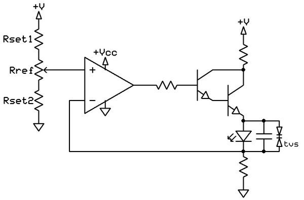
Here is a schematic along with a PSPICE step response. You can see the op-amp reaching equilibrium (the simulation assumes that the potentiometer is maxed, setting the current to 2A) in the step response, and there is no current overshoot. Also, even if the potentiometer is scratchy, rather than send too much current, it will send very low current.


This could be improved with LASASORB, and is not very efficient (because the laptop output is 18V and most of that voltage has to be dissipated in resistors), but I was trying to make a simple, safe driver to run off of most laptop chargers.

The source could also drive multiple diodes in series (because of the huge 18V overhead).

***YOU MUST USE POWER RESISTOR FOR R7 and R1!!! R7 is not necessary but if you use it, USE A POWER RESISTOR***

Any critiques or suggestions are appreciated,

John
 

Attachments

  • currentsourceschematic.png
    currentsourceschematic.png
    95.3 KB · Views: 1,147
  • step-responsecurrentsource.png
    step-responsecurrentsource.png
    70.4 KB · Views: 540
Last edited:


Joined
Jan 16, 2011
Messages
22
Points
0
Can't you run it with a lower voltage source? 18 V is kind of overkill...

Yes, very easily. I agree 18V is overkill, but I made it specifically to run off of any laptop charger.

Depending on what voltage you use you would need to remove the 2.47Ohm resistor between the power supply and the darlington pair (the two transistors next to the output.)

For example, with 9V, just change the 2.47 Ohm to 1 Ohm.

The maximum current output could also easily be increased linearly by varying the 22kOhm (for example changing it to 44kOhm (or near there) would cause it's maximum output current to be 4 Amps. I have mine capped at 2A just because that is where the diodes I plan on using burn.

-John
 
Last edited:

Benm

0
Joined
Aug 16, 2007
Messages
7,896
Points
113
You should power drivers like this one from much lower voltages. 12 volts is overkill already, i'd consider 9 volts as an accaptable maximum.

It will work from 18 volts, but prepare to heatsink the transistor properly!
 
Joined
Jan 16, 2011
Messages
22
Points
0
I don't mean to be rude, but can you read? I mentioned that in the original post. Then someone else made a remark about it and I explained it again.

The driver is 18V because I want to drive it from any laptop supply!! I know it is overkill!!

If you want to use a lower voltage you can easily lower it if you have a different DC supply capable of 2+ amps. One upside to the fact that it has a large supply voltage is that it could power 2-3 diodes at a time.
 

GBD

0
Joined
Oct 25, 2010
Messages
783
Points
0
Ive done a driver simular to this in the past, but just used a pair of transistors and a pot as a referance point instead of what you are currently using. (same concept, but I belive its just less part count)
That is to set a minimum and a maximum and then a pot for me to adjust, but as to not exceed any of the two.

Also, Id ditch the 2 transistors in parralel (that, and get a newer less lossy transistor) and use a darlington pair instead, last time ive done this, I had no heating issues with the darlington, but single/parrel transistors where either too bulky or fryed on me.

Id also put a capacitor across the diode, just so that you have a rise/fall upon turn off or turn on, and also put a TVS diode across it as well, bieng to catch any quick transients and overvoltage states. (I used a small SMD TVS diode, 600W peak IIRC, more then plenty, but the 1.5KE series will work nicely too).

Other then that.. I really dont see anything bad about this circuit.
Heres the one I made a while ago:

drivetrbmp.jpg
 
Joined
Jan 16, 2011
Messages
22
Points
0
Also, Id ditch the 2 transistors in parralel (that, and get a newer less lossy transistor) and use a darlington pair instead, last time ive done this, I had no heating issues with the darlington, but single/parrel transistors where either too bulky or fryed on me.

If you look that is a darlington transistor. The transistors are not in parallel but hooked up in a darlington configuration. A darlington pair is not a specially made device, but two NPN bjt's with collectors connected, and the emitter of the first BJT feeding the base of the second. The total gain is then beta1*beta2.

What do you mean by "lossy" transistor?
If you use a darlington pair made with transistors which have too high of a beta value (my darlington pair consists of a 2N2222A with a beta of 300 followed by a power transistor with a beta of 70) the circuit will oscillate around the set point. This happens because the slew rate of the op amp is slower than that of the transistors. As the op-amp increases it's output slightly, the transistors send too much current. The op-amp then adjusts its output, but again overshoots low. This will continue unless the amplification of the transistors is limited.

Id also put a capacitor across the diode, just so that you have a rise/fall upon turn off or turn on, and also put a TVS diode across it as well, bieng to catch any quick transients and overvoltage states. (I used a small SMD TVS diode, 600W peak IIRC, more then plenty, but the 1.5KE series will work nicely too).

What is a TVS diode? I have an old power supply from my computer I've taken apart and it has a 3 terminal, transistor looking thing. Printed on it is the circuit symbol from your diagram (two diodes going into each other). Is this the same thing as a TVS diode?

Thanks,

John
 

GBD

0
Joined
Oct 25, 2010
Messages
783
Points
0
What I meant by lossy transistor, is these older 2n2222's (So any of the TIP series for that matter) have terrible power dissapation, hence why I kept burning them up all the time, not so much the 2n2222's, but the TIPs.. so thats a transistor thats on my -throw it in the trash- parts list. I wont even bother with those things for anything like this.

Also, sorry about that, I didnt see that base connected, for some reason my eyes played a bit of a trick on me, leading me to belive you parraleled two transistors, not put them in darlington config, so nevermind on that. (Gotta look closer next time :) )

A TVS diode is a transient mode/voltage activated diode, most of them have a reverse recovery voltage rating, and a clamping voltage, the clamping voltage bieng where the diode fully conducts if exceeded. (it will behave a bit like a zener when you are just below its clamping voltage, before it fully switches on. This is not linear either.

These diodes are meant to stop transients by shorting out the part they are protecting and letting themselves take the abuse so to speak. they cannot handle large surges or continous conduction without damage, but this is what they are designed for. you are sacrificing this TVS diode in place of a far more expensive part (your LD).

That bieng said, over voltage spikes, static, etc, will activate the diode and cause it to short out the laser diode so the chances for LD harm is minimal.

About the 3 terminaled part you found, it is mosty likly a schottkey diode pair in a single package (I assume TO-247 or simular sized package?). all TVS diodes ive seen come in 2 lead (thru-hole or SMD) packages. (barrel style), so dont use that for this application.

Go either on littlefuse or ST micro, littlefuse has a pretty nice selection of these diodes, and ST goes by the name of "Transil" for thiers, either will work so long your clamping voltage is above your operating voltage, else you will just kill this tvs, again, due to the design of it bieng made for transient conduction, not continous, but they are a great little part and have a very fast responce time compared to snubbers or other methods of surge/spike suppression.

Hope that clears it up a little.
 
Last edited:
Joined
Jan 16, 2011
Messages
22
Points
0
Thanks GDB. Do you know if two zeners in parallel, pointing opposite directions across the laser diode (with Vzk~5V) would work the same way?

Thanks,

John
 
Joined
Feb 1, 2008
Messages
2,894
Points
0
Hey guys, great discussion here! I like your ideas, nice circuits here.
 

GBD

0
Joined
Oct 25, 2010
Messages
783
Points
0
It will be a bit tricky to set up, but Im sure it will work as well.
Zeners are no where near fast or sensative as TVS is, but it will do the job for surges (cant say anything about ESD though).

Ive used a zener setup like you mention to protect the gates of power IGBTs/MOSFETs before, and they work just fine in preventing gate overvoltage (For my stuff, I usually pulse several hundred amps through the IGBTs, so gate saturation is needed to exploit the IGBT's current capabilities, that bieng said im driving them close to thier gate's maximum ratings... zeners definatly prevent death.)

So yeah, you can use them, but if you want a foolproof and more reliable method, id get a TVS diode.. they are a few cents anyway :)


Top