

- Joined
- Dec 25, 2009
- Messages
- 1,251
- Points
- 48
This is still a real WIP. I'm writing bits between classes and such. (Had some formatting issues so I switched some of the text to pictures).
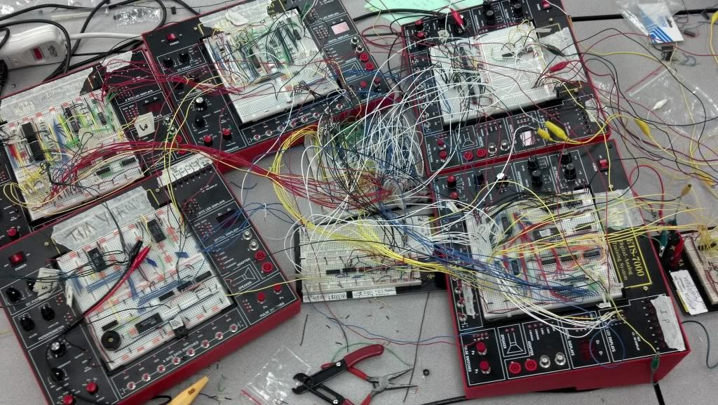
The processor I built from scratch:
Some terminology:
bit - a signal either 'off' or 'on' --> '0' or '1'
nibble - 4 bits (e.g. "0100")
byte - 8 bits (e.g. "10010110")
kilobyte - 1024 bytes
This will give you guys a better idea of how devices like computers and our phones work and process. It'll go into the basic functioning and then some limitations that most people don't know.
This will also help you understand and I'll also explain why processor clock speed actually really doesn't matter that much and also why small optimizations in code (i.e. 30% "speed increase" or less) really actually are insignificant and inconsequential. If you have any questions feel free to ask!
Part 1:
The very most basic fundamentals of processing…. 0s and 1s!!:
Put your minds in base 2 (binary). That is, counting from 0 to 5 goes like this: 0, 1, 10, 11, 100, 101. Addition, subtraction, multiplication, etc all still work the same way and you can do it all by hand in the same way.
Lots of you (undoubtedly all of you) know that binary has something to do with how computers work. I'm willing to bet that almost none of you, however, could tell me how electricity, some computer chips, and wires can tell me that 1101 + 0111 = 10100.
The trick is logic. Computer processing is completely and entirely built on various groupings of logic functions and truth tables (e.g. AND [i.e. 0 AND 0 is 0…. 0 AND 1 is 0…. 1 AND 1 is 1], OR, XOR, NOT, etc). A truth table is basically just a visual representation of the logic functions, for example:
A XOR B -- XOR, or "exclusive or" is like saying "A OR B but not A AND B"
In fact, you could theoretically build an entire processor using nothing but the logic function NAND, but that would be exceedingly stupid and time, space, and speed wasting.
So, how does one construct a "gate" that takes two signals and translates it into the result? The easiest way to visualize this is water "gates." If you have a bucket with two hoses (inputs) feeding into one side of the bucket and one hose (output) feeding out of the other side, you can make different "gates" by varying the design of the bucket. For example, if you put a hole in the bottom that is the same size as one of the input hoses, you have built an "AND" gate. If water pumps in through both of the input hoses, the bucket can't drain fast enough to prevent water from reaching the output hose so the output hose will expel water (a "1") only when both of the input hoses are pumping water in (1 AND 1 is 1). However, if only one hose is on, the hole in the bottom will be able to drain it and the output hose will be a "0." To make an "OR" gate, you could just make the output hose stick out of the bottom of the bucket. So, yes, you COULD make a computer that runs on flowing water… but electricity runs a <sarcasm>teensy</sarcasm> bit faster and cleaner than water in buckets…
Making addition:
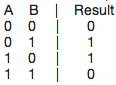
So, how does, say, addition rise out of these logic gates? It's actually oddly simple… You first write up a truth table for what you are trying to accomplish -- in this case let's do 1 bit addition.
A + B = Result
(Since we are only using 1 bit, we can't express that 1 + 1 = 10 (we have an overflow error)).
Now that we have the truth table, all we need to do is figure out what logic function(s) ties together A and B so that the output is Result! If you don't recognize it, it's simply A XOR B YAY! We've built a 1-bit adder… kind of!
Building a better one bit adder takes a slightly bigger truth table (and you can see where this starts getting a bit complex….).
[a potential carry in bit] + A + B = [a potential carry out bit] Result
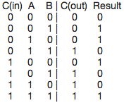
There are several techniques and tricks and rules (similar to the type of rules you would use to factor x(x+2) into x^2 + 2x) that can be used to help solve bigger truth tables but I won't get into them because they are relatively insignificant for understanding how these work. The logic works as follows for the above table (note these may be simplify-able but I'm lazy ):

So now you can build a 1 bit adder with a carry in and carry out using the logic above. Therefore, you can build an x-bit adder by stringing a bunch of 1 bit adders together (the previous C(out) leads into the next C(in)). Simple! That's how pretty much all processes are built -- logic!
Key parts of a really basic processing unit (note: a "clock" is an input into basically every single component of a processor. The clock signal is what tells things "okay, next step" so everything can move on to the next step. A 1.2GHz processor will "clock" the system 1.2 billion times per second):
Incrementor: Incrementors add 1 to a number on each "clock" cycle (this is how a processor will step through instructions in addresses in RAM).
Flip-flop (also called a "latch"): Super basic memory storage. Can be simply made with cross-coupled NOR gates. (See: http://en.wikipedia....ile:R-S_mk2.gif)
Register: Usually a series of latches (so we can store, for example, a byte rather than a bit). Stores a single input value for later access when "clock"ed. When clocked again, the old value is overwritten to make way for the next input signal. This type of memory is volatile -- i.e. when the power goes off, **poof** this stuff is gone.
Multiplexor: Multiplexors take in multiple inputs but have only one output. There is a 'deciding' input that tells which of the multiple inputs to output (e.g. there may be 4 inputs to the multiplexor (000, 010, 011, 110 [random]) with a deciding input of 01. This means that the 2nd input, 010, will be the output of the multiplexor when a clock signal arrives.
This list may grow….
And yes, all the above can be constructed with logical combinations.
Part 2:
Basic layout of my 8-bit processor
There are quite a few parts to a basic processor like the one depicted above. It's the general idea of how processors work, but ultra simplified!
Main Memory -- the "RAM" or really what stores the lines of code. The processor can also load, jump to, and store to different memory locations. Each memory address is an 8-bit address (meaning there are 256 [2^8] possible memory slots). Each 8-bit address holds 1 byte of information (the 'word' size is 8 **more on this later**).
Instruction pointer -- an incrementer that is incremented by a clock cycle. Starts at 0 (code put into Main Memory should start at memory address 0) and increments until it receives a "HALT" signal.
Accumulator -- the output of everything. All results to all commands and instructions will be displayed on the accumulator.
Control Unit -- dispatches the necessary deciding/control bits for various multiplexors, read/write enables, and any other controls that other components in the processor might need. The input is whatever the operator is in the current instruction (**more on this in the next section**).
Branching Control -- controls "branching." Branching is where if a given condition is satisfied, the instruction pointer will 'jump' to a different specified memory location (this is how loops work!). This control will make sure the processor branches without messing anything else up.
Arithmetic Logic Unit (ALU) -- one piece of the processor that handles all the math stuff it takes in two input 'words' and, via a multiplexor controlled by the control unit, outputs the result you are looking for.
So, you have an instruction pointer that starts at 0 and increments on every clock press. There is a program in Main Memory starting at address zero. The first line of code will have some instruction in it's upper 4 bits, and an operand (**more on this in the next section**) in the lower 4 bits. The instruction gets broken off and taken to several locations (the main of which is the control unit). The lower four bits get broken off and taken elsewhere. The signals flow through and the accumulator is set to whatever results from this line of code.
Example:
Addition program:
Instruction 00000000: First you set the accumulator to a certain number (e.g. 00110110) [you technically have to do this in two steps--set lower nibble and set upper nibble--but I'm consolidating it now for simplicity's sake]
Instruction 00000001: Then you copy that number into one of the four available registers (we could only have four registers in the processor for an 8-bit machine since you need to be able to specify two registers per command **more on this in the next section**) [e.g. to register A]
Instruction 00000010: Then you set the accumulator to another number (e.g. 00000011)
Instruction 00000011: Then you copy that number into a different register (you can't overwrite the register you already used or that first number will be totally gone!) [e.g. to register B]
Instruction 00000100: Then you send the command to add register A to register B --> the accumulator will now read 00111001
Part 3:
It's all just words...
What is a 'word'? A word is what a single unit of information is called. The word size varies by processor -- a 32-bit processor has, you guessed it, 32-bit words! That means each individual word is 32 bits long. The processor I built in my project *above* was an 8-bit processor -- 8-bit word size. In my processor, 4 of the 8 bits were dedicated to a certain command (an instruction or operator as discussed above) and the last 4 bits were the arguments of that particular command (for example, registers or bits you want to set the accumulator to). Word size also determines the amount of available memory a computer can access. Since everything needs an "address," if you've got a 32-bit processor and 32-bit word size, that means you can only generate/access 2^32 different address spaces (or around 4GB of memory ---> ahhhhhhhh, I see!). Hence the recent transition to 64-bit systems (4GB cap on memory [incl RAM] just isn't a lot anymore --> 2^64 [64-bit word size] gives us a 17 billion GB cap on memory).
Since in my processor we had an 8-bit word size, we could only use 4 bits for the operator, and therefore we could only have 2^4, or 16 commands. The commands were as follows:
HALT (stops the entire program)
LOAD (loads a value from Main Memory)
STOR (stores a value to a location in Main Memory)
AND ("and"s the bits of two numbers bit-wise)
OR ("or"s the bits of two numbers bit-wise)
NOT ("not"s the bits of one number bit-wise)
ADD (add two numbers)
SUB (subtract two numbers)
SEQ (displays a "1" if two numbers are equal)
SLT (displays a "1" if first number is less than second)
SGT (displays a "1" if first number is greater than second)
COPY (copies a value from accumulator [output] to a register)
SLA (sets the lower 4 bits of the accumulator to a specified 4 bits)
SUA (sets the upper 4 bits of the accumulator to a specified 4 bits)
BRIS (Branch if set [basically done for a kind of loops while reading from memory])
BRIC (Branch if clear [another way to do loops])
Each of these commands is assigned a different 4-bit pattern. For example, "COPY" was 0001, "ADD" was 0101, "SLA" was 1110, and "SUA" was 1111. The four registers, A, B, C, and D were each assigned 2-bit patterns 00, 01, 10, 11 respectively. Guess what... now we can write the addition program that I went through earlier in binary (unconsolidated)!
Addition program:
First you set the accumulator to a certain number (e.g. 00110110)
SLA to 0110 ==> 1110 0110
SUA to 0011 ==> 1111 0011
**accumulator will now read '00110110'**
Then copy that number to register A
COPY to 00xx ==> 0001 00xx [the 'xx' means that anything can go there and it doesn't matter]
Then set the accumulator to another number (e.g. 00000011)
SLA to 0011 ==> 1110 0011
SUA to 0000 ==> 1111 0000 **this command technically isn't necessary since SLA in this design will set the accumulator to 00000000 prior to setting values**
**accumulator will now read '00000011'**
Then copy that number into register B
COPY to 01xx ==> 0001 01xx
Then send the command to add register A to register B
ADD 00 and 01 ==> 0101 00 01
**accumulator will now read '00111001'**
Here it all is together")
Memory location What's in it
0b00000000: 11100110
0b00000001: 11110011
0b00000010: 000100xx
0b00000011: 11100011
0b00000100: 11110000
0b00000101: 000101xx
0b00000110: 01010001
0b00000111: 00000000 [HALT]
You can see how more commands and capabilities become available as the word size increases from 8 bits to 32 bits and even to 64 bits. With a 64 bit word size you can have 32 bits dedicated to the operator, which allows 2^32 possible instructions (vs. 2^4 for my 8-bit processor).
If you know how hex works and why it's used go ahead and skip this next paragraph!
When you have an 8-bit word size, it's not that hard to write a command in binary (e.g. 01010001). When you have a 32-bit word size, however, there's gotta be an easier (and clearer) way to write a command than 10101001010010001010110110110101 (you can imagine how big 64-bit would be...). So now we are led to hexadecimal, or a base 16 numbering system. In this, we split the command into nibbles. Each nibble gets it's own hexadecimal digit (counting in hex goes as follows: 0, 1, 2, 3, 4, 5, 6, 7, 8, 9, A, B, C, D, E, F, 10, 11, 12, 13, 14, 15, 16, 17, 18, 19, 1A, 1B, 1C, 1D, 1E, 1F, etc). You can see how these cleans up the binary: 0b01010001 [b for binary] becomes 0x51 [x for hex] (0101 --> 5 and 0001 --> 1).
Part 4:
Processor speed/limitations AND why processor speed nowadays really doesn't matter..
So tell me.. what determines a processor speed? Most would say, "clock speed" (i.e., 3.0GHz is faster than 1.2GHz). What would you say if I told you that a 6.0GHz processor would be no faster than a 3.0GHz processor? Well it's true.. There actually is a current limit in clock speed because at this point increasing clock speed does absolutely nothing (which is why processor designers have moved to multiple cores + smaller processors). Actually, processors would be far less effective without something called 'pipelining.' First, however, I'll explain why increasing the clock speed doesn't increase the speed of the processor past a certain point.
Limit 1: You have the actual speed of the electrical signals. Imagine again a processor made of water gates I explained above. If you were to send clock signals to a series of connected water gates at a rate of even 5 times a second (let alone 2 billion times a second), you could intuitively see the problem that we'd have -- the clock speed is faster than the signals can even flow through the processor. The same situation arises when you are sending a clock signal to the processor at billions of times per second.
Limit 2 (the BIG one): Hierarchy of Cache, RAM, and even HD speed. Sure the registers in the processor itself can handle the clock speed, but can the cache, RAM, and HD? As you get bigger and bigger storage spaces (more and more addresses), it takes longer and longer to look up the piece of memory you are trying to find. The materials also get more and more expensive (A LOT MORE). It's fine to use expensive (and very fast) electronics for, say, the registers and cache because those are so small and there are so few that it's not costly. However, when you hit RAM and a HD, the cost skyrockets.
Say your processor is a 1GHz processor, so you are clocking 1 billion times per second. That means you are clocking once per nanosecond. The access time for a register is that -- one nanosecond [these are ballparks from within the past 5 years]. The lookup time in the cache is more -- two nanoseconds (which means if you are accessing the cache, you will already have a wasted clock cycle ON TOP OF all the clock cycles that go by as the signals are flowing through all the gates/other parts of the processor). The lookup time in RAM is even larger -- ten nanoseconds (9 "wasted" clock cycles while you're waiting for what you asked for). The lookup time in a hard drive is 10,000,000 nanoseconds (solid state drives lower this by about a factor of 10) -- if we didn't have a cache or main memory, our devices would be unbelievably slow...
DEVICE SPEED IS LIMITED BY THE WEAKEST LINK (longest path) IN THE HARDWARE.
So, you ask, if even the register lookup time (by far the fastest memory in the processor) is barely 'good enough' for a 1GHz processor, why do we have 3GHz processors? This is thanks to a lovely thing called pipelining. How I've described a processor thus far is you have an instruction that flows through the processor until the accumulator spits out the answer (meanwhile you've wasted a bunch of clock cycles doing nothing [remember: just the lookup in a register takes the same amount of time as a single clock cycle -- the signals still need to flow through all sorts of gates and parts before reaching the accumulator]).
This is like building a car factory that starts with the instructions of how to build the car. When you send a clock signal to the factory they start building a car and the process flows through until a car is spit out the other end (you can keep sending clock cycles as fast as you want -- they won't start the next car until the previous car is spit out the other end). Pipelining is breaking that up into chunks (or like creating an assembly line in the factory), so that on each clock press, another answer (or car) can be spit out the other end -- this allows us to increase processor speed without wasting a ton of cycles. There is a limit to this too, because there is a limit to how many chunks you can break a single processor into [around 20 I believe] (which is why we've hit a limit around 3-4GHz).
So next time you're shopping for a device, you should realize that a 1.8GHz processor is really not going to make a big difference compared to a 3GHz processor, because while clock speeds kind of matter, the actual process itself is hugely limited by the slow speed of RAM and the HD. In fact, I'd even prefer a <2GHz processor with a solid state hard drive over a 3+GHz processor with a regular hard drive (unless you're doing something really processor-intensive.. in which case you probably need that extra speed!). Fast RAM also really helps.
Part 5:
Super brief caching explanation and why some optimizations are useless.
All of you have heard of a "cache." But what is it?? It makes the device faster. Yeah, but how?? Well... the "how" is actually still being debated. A cache's job is to store data that is likely to be used so you don't have to go to RAM to access that same information (since RAM [read part 4] is slow and big -- cache is small(er) and fast). So "how" is this done?? It's tricky, because you're supposed to tell what data is "likely to be used," which means a perfect cache is one that can see into the future and therefore store all the particular addresses/bytes that are GOING TO BE accessed. This is clearly not possible so we need to resort to other theories/algorithms/what have you. The main two are what are known as "temporal locality" and "spacial locality." These are relatively self-explanatory:
Temporal locality states that things that were recently used are likely to be used again soon.
Spacial locality states that data in memory close to data that was just used are likely to be used.
Stuff like this (as well as sometimes some randomness and statistical analysis) go into making a caching system. The caching system can't be too big, or else it just turns into another slow RAM -- but it can't be too small, or else it won't be worth it. A super duper basic caching system that is not used today would be a 1:1 ratio of metadata to data, meaning that each entry in the cache has one 'word' as an address (metadata) and one set of data stored at that address. What caching systems do nowadays is cleverly lower the amount of metadata:data ratio by doing things like paging. I won't get in to that because it gets a bit complicated -- if you're going to Google it and search for it it would be helpful to look up "Virtual Memory" as well, which is a cool little thing that the ancients thought up that allows programmers to not worry about actual address locations (basically creates a "fake" memory that maps itself to real address spaces -- helps with sandboxing, memory managements, everything!).
So, a cache has a set of metadata (you can think of them as memory addresses) that map to certain data. This data is supposed to be data that is going to be used soon (in an ideal caching system). Basically a tiny RAM (note: if we made RAM out of the same fast materials as caches, costs would be actually ridiculous)! Since we can't store everything in RAM in caches, we need a sort of 'hashing function' that'll map the data we want to cache to various metadata in the cache. What happens if the hashing function (it's not really a hash function, but it's close so it's what I'll call it for simplicity's sake) tries to map data to metadata that is already holding on to some data is called a "collision." You'd want to eliminate collisions as much as possible because you want to utilize the whole cache, you do NOT want to just keep swapping out data back to RAM and then back to the cache because two pieces of data by chance map to the same metadata in the cache (we want to touch RAM as little as possible).
I basically just condensed about a months worth of college classes into two paragraphs so I wouldn't expect you at this point to fully understand -- basically, caches store information that they think (via spacial/temporal locality) will be used soon in order to avoid spending a lot of CPU time fetching the information from RAM (and, even worse, the Hard Drive). What's cool is they've gotten so good at this that caches actually end up being HUGELY used (like... a vast majority of the time). That's why we can stand the speed of our devices (most of the time).
SO, to the FUN part! Why are most optimizations useless?? It came from an interesting study done by some grad student and his professor. They were testing actual differences in O2 and O3 arguments to a gcc compiler (some of you will know what that is -- basically you have certain levels [1, 2, 3, 4] for the compiler that are supposed to optimize the code. Each one takes longer than the previous of course but each step up is supposed to optimize further [finds more optimizations]). So, what did he find? The grad student found that the O3 option gave a 30% increase in performance when compared to the O2. Woo!! So he gave his results to his professor. The professor then tried the same test with the same code to verify but he found something different -- a 15% decrease in performance. What?? The professor came back "you're an idiot you did something wrong do it again." So the student did it again... got the same result: 30% increase. This was weird.. so they both sat down at the same machine -- the student ran it: 30% increase. The professor then sat down at the machine and ran the EXACT same code through the compiler and ran it: 15% decrease in performance. Quite literally, what the f**k??
They spent months trying to figure out why this was happening. Turns out, the professor had been at the school longer than the student so his PATH variable was longer. THIS was causing the huge performance difference. With a larger PATH variable, all the objects in memory were shifted a teensy bit in one direction. This simply by chance ended up causing more collisions when the professor ran the program than when the student did. This is literally one of thousands of different variables that can affect performance in the same way. For example, there are cases of "dead code." Yes, it's called "dead code," where randomly adding in useless lines of code that are NEVER run or reached can significantly increase or decrease performance on some systems simply because the memory placement/shifting results in fewer or more collisions in your cache by chance. In fact, Microsoft spends weeks with rooms full of servers twiddling all the different variables with all sorts of compilers and different systems to find the best possible configuration for their software.. Even then they can't really make it perfect -- there are just too many variables and too much variation in systems. For this odd reason, most "optimizations" that are within ~30% are generally useless, because they simply won't work on every system.
THIS IS ALSO PART OF A REASON THAT BENCHMARKS SUCK. There are so many problems with benchmarks... You need a ton of different benchmarks averaged with a ton of twiddled variables to get a somewhat truly decent idea of what's going on!
Next... No clue. Suggest something!
The processor I built from scratch:
Some terminology:
bit - a signal either 'off' or 'on' --> '0' or '1'
nibble - 4 bits (e.g. "0100")
byte - 8 bits (e.g. "10010110")
kilobyte - 1024 bytes
This will give you guys a better idea of how devices like computers and our phones work and process. It'll go into the basic functioning and then some limitations that most people don't know.
This will also help you understand and I'll also explain why processor clock speed actually really doesn't matter that much and also why small optimizations in code (i.e. 30% "speed increase" or less) really actually are insignificant and inconsequential. If you have any questions feel free to ask!
Part 1:
The very most basic fundamentals of processing…. 0s and 1s!!:
Put your minds in base 2 (binary). That is, counting from 0 to 5 goes like this: 0, 1, 10, 11, 100, 101. Addition, subtraction, multiplication, etc all still work the same way and you can do it all by hand in the same way.
Lots of you (undoubtedly all of you) know that binary has something to do with how computers work. I'm willing to bet that almost none of you, however, could tell me how electricity, some computer chips, and wires can tell me that 1101 + 0111 = 10100.
The trick is logic. Computer processing is completely and entirely built on various groupings of logic functions and truth tables (e.g. AND [i.e. 0 AND 0 is 0…. 0 AND 1 is 0…. 1 AND 1 is 1], OR, XOR, NOT, etc). A truth table is basically just a visual representation of the logic functions, for example:
A XOR B -- XOR, or "exclusive or" is like saying "A OR B but not A AND B"
In fact, you could theoretically build an entire processor using nothing but the logic function NAND, but that would be exceedingly stupid and time, space, and speed wasting.
So, how does one construct a "gate" that takes two signals and translates it into the result? The easiest way to visualize this is water "gates." If you have a bucket with two hoses (inputs) feeding into one side of the bucket and one hose (output) feeding out of the other side, you can make different "gates" by varying the design of the bucket. For example, if you put a hole in the bottom that is the same size as one of the input hoses, you have built an "AND" gate. If water pumps in through both of the input hoses, the bucket can't drain fast enough to prevent water from reaching the output hose so the output hose will expel water (a "1") only when both of the input hoses are pumping water in (1 AND 1 is 1). However, if only one hose is on, the hole in the bottom will be able to drain it and the output hose will be a "0." To make an "OR" gate, you could just make the output hose stick out of the bottom of the bucket. So, yes, you COULD make a computer that runs on flowing water… but electricity runs a <sarcasm>teensy</sarcasm> bit faster and cleaner than water in buckets…
Making addition:
So, how does, say, addition rise out of these logic gates? It's actually oddly simple… You first write up a truth table for what you are trying to accomplish -- in this case let's do 1 bit addition.
A + B = Result
(Since we are only using 1 bit, we can't express that 1 + 1 = 10 (we have an overflow error)).
Now that we have the truth table, all we need to do is figure out what logic function(s) ties together A and B so that the output is Result! If you don't recognize it, it's simply A XOR B YAY! We've built a 1-bit adder… kind of!
Building a better one bit adder takes a slightly bigger truth table (and you can see where this starts getting a bit complex….).
[a potential carry in bit] + A + B = [a potential carry out bit] Result
There are several techniques and tricks and rules (similar to the type of rules you would use to factor x(x+2) into x^2 + 2x) that can be used to help solve bigger truth tables but I won't get into them because they are relatively insignificant for understanding how these work. The logic works as follows for the above table (note these may be simplify-able but I'm lazy ):
So now you can build a 1 bit adder with a carry in and carry out using the logic above. Therefore, you can build an x-bit adder by stringing a bunch of 1 bit adders together (the previous C(out) leads into the next C(in)). Simple! That's how pretty much all processes are built -- logic!
Key parts of a really basic processing unit (note: a "clock" is an input into basically every single component of a processor. The clock signal is what tells things "okay, next step" so everything can move on to the next step. A 1.2GHz processor will "clock" the system 1.2 billion times per second):
Incrementor: Incrementors add 1 to a number on each "clock" cycle (this is how a processor will step through instructions in addresses in RAM).
Flip-flop (also called a "latch"): Super basic memory storage. Can be simply made with cross-coupled NOR gates. (See: http://en.wikipedia....ile:R-S_mk2.gif)
Register: Usually a series of latches (so we can store, for example, a byte rather than a bit). Stores a single input value for later access when "clock"ed. When clocked again, the old value is overwritten to make way for the next input signal. This type of memory is volatile -- i.e. when the power goes off, **poof** this stuff is gone.
Multiplexor: Multiplexors take in multiple inputs but have only one output. There is a 'deciding' input that tells which of the multiple inputs to output (e.g. there may be 4 inputs to the multiplexor (000, 010, 011, 110 [random]) with a deciding input of 01. This means that the 2nd input, 010, will be the output of the multiplexor when a clock signal arrives.
This list may grow….
And yes, all the above can be constructed with logical combinations.
Part 2:
Basic layout of my 8-bit processor
There are quite a few parts to a basic processor like the one depicted above. It's the general idea of how processors work, but ultra simplified!
Main Memory -- the "RAM" or really what stores the lines of code. The processor can also load, jump to, and store to different memory locations. Each memory address is an 8-bit address (meaning there are 256 [2^8] possible memory slots). Each 8-bit address holds 1 byte of information (the 'word' size is 8 **more on this later**).
Instruction pointer -- an incrementer that is incremented by a clock cycle. Starts at 0 (code put into Main Memory should start at memory address 0) and increments until it receives a "HALT" signal.
Accumulator -- the output of everything. All results to all commands and instructions will be displayed on the accumulator.
Control Unit -- dispatches the necessary deciding/control bits for various multiplexors, read/write enables, and any other controls that other components in the processor might need. The input is whatever the operator is in the current instruction (**more on this in the next section**).
Branching Control -- controls "branching." Branching is where if a given condition is satisfied, the instruction pointer will 'jump' to a different specified memory location (this is how loops work!). This control will make sure the processor branches without messing anything else up.
Arithmetic Logic Unit (ALU) -- one piece of the processor that handles all the math stuff it takes in two input 'words' and, via a multiplexor controlled by the control unit, outputs the result you are looking for.
So, you have an instruction pointer that starts at 0 and increments on every clock press. There is a program in Main Memory starting at address zero. The first line of code will have some instruction in it's upper 4 bits, and an operand (**more on this in the next section**) in the lower 4 bits. The instruction gets broken off and taken to several locations (the main of which is the control unit). The lower four bits get broken off and taken elsewhere. The signals flow through and the accumulator is set to whatever results from this line of code.
Example:
Addition program:
Instruction 00000000: First you set the accumulator to a certain number (e.g. 00110110) [you technically have to do this in two steps--set lower nibble and set upper nibble--but I'm consolidating it now for simplicity's sake]
Instruction 00000001: Then you copy that number into one of the four available registers (we could only have four registers in the processor for an 8-bit machine since you need to be able to specify two registers per command **more on this in the next section**) [e.g. to register A]
Instruction 00000010: Then you set the accumulator to another number (e.g. 00000011)
Instruction 00000011: Then you copy that number into a different register (you can't overwrite the register you already used or that first number will be totally gone!) [e.g. to register B]
Instruction 00000100: Then you send the command to add register A to register B --> the accumulator will now read 00111001
Part 3:
It's all just words...
What is a 'word'? A word is what a single unit of information is called. The word size varies by processor -- a 32-bit processor has, you guessed it, 32-bit words! That means each individual word is 32 bits long. The processor I built in my project *above* was an 8-bit processor -- 8-bit word size. In my processor, 4 of the 8 bits were dedicated to a certain command (an instruction or operator as discussed above) and the last 4 bits were the arguments of that particular command (for example, registers or bits you want to set the accumulator to). Word size also determines the amount of available memory a computer can access. Since everything needs an "address," if you've got a 32-bit processor and 32-bit word size, that means you can only generate/access 2^32 different address spaces (or around 4GB of memory ---> ahhhhhhhh, I see!). Hence the recent transition to 64-bit systems (4GB cap on memory [incl RAM] just isn't a lot anymore --> 2^64 [64-bit word size] gives us a 17 billion GB cap on memory).
Since in my processor we had an 8-bit word size, we could only use 4 bits for the operator, and therefore we could only have 2^4, or 16 commands. The commands were as follows:
HALT (stops the entire program)
LOAD (loads a value from Main Memory)
STOR (stores a value to a location in Main Memory)
AND ("and"s the bits of two numbers bit-wise)
OR ("or"s the bits of two numbers bit-wise)
NOT ("not"s the bits of one number bit-wise)
ADD (add two numbers)
SUB (subtract two numbers)
SEQ (displays a "1" if two numbers are equal)
SLT (displays a "1" if first number is less than second)
SGT (displays a "1" if first number is greater than second)
COPY (copies a value from accumulator [output] to a register)
SLA (sets the lower 4 bits of the accumulator to a specified 4 bits)
SUA (sets the upper 4 bits of the accumulator to a specified 4 bits)
BRIS (Branch if set [basically done for a kind of loops while reading from memory])
BRIC (Branch if clear [another way to do loops])
Each of these commands is assigned a different 4-bit pattern. For example, "COPY" was 0001, "ADD" was 0101, "SLA" was 1110, and "SUA" was 1111. The four registers, A, B, C, and D were each assigned 2-bit patterns 00, 01, 10, 11 respectively. Guess what... now we can write the addition program that I went through earlier in binary (unconsolidated)!
Addition program:
First you set the accumulator to a certain number (e.g. 00110110)
SLA to 0110 ==> 1110 0110
SUA to 0011 ==> 1111 0011
**accumulator will now read '00110110'**
Then copy that number to register A
COPY to 00xx ==> 0001 00xx [the 'xx' means that anything can go there and it doesn't matter]
Then set the accumulator to another number (e.g. 00000011)
SLA to 0011 ==> 1110 0011
SUA to 0000 ==> 1111 0000 **this command technically isn't necessary since SLA in this design will set the accumulator to 00000000 prior to setting values**
**accumulator will now read '00000011'**
Then copy that number into register B
COPY to 01xx ==> 0001 01xx
Then send the command to add register A to register B
ADD 00 and 01 ==> 0101 00 01
**accumulator will now read '00111001'**
Here it all is together
Memory location What's in it
0b00000000: 11100110
0b00000001: 11110011
0b00000010: 000100xx
0b00000011: 11100011
0b00000100: 11110000
0b00000101: 000101xx
0b00000110: 01010001
0b00000111: 00000000 [HALT]
You can see how more commands and capabilities become available as the word size increases from 8 bits to 32 bits and even to 64 bits. With a 64 bit word size you can have 32 bits dedicated to the operator, which allows 2^32 possible instructions (vs. 2^4 for my 8-bit processor).
If you know how hex works and why it's used go ahead and skip this next paragraph!
When you have an 8-bit word size, it's not that hard to write a command in binary (e.g. 01010001). When you have a 32-bit word size, however, there's gotta be an easier (and clearer) way to write a command than 10101001010010001010110110110101 (you can imagine how big 64-bit would be...). So now we are led to hexadecimal, or a base 16 numbering system. In this, we split the command into nibbles. Each nibble gets it's own hexadecimal digit (counting in hex goes as follows: 0, 1, 2, 3, 4, 5, 6, 7, 8, 9, A, B, C, D, E, F, 10, 11, 12, 13, 14, 15, 16, 17, 18, 19, 1A, 1B, 1C, 1D, 1E, 1F, etc). You can see how these cleans up the binary: 0b01010001 [b for binary] becomes 0x51 [x for hex] (0101 --> 5 and 0001 --> 1).
Part 4:
Processor speed/limitations AND why processor speed nowadays really doesn't matter..
So tell me.. what determines a processor speed? Most would say, "clock speed" (i.e., 3.0GHz is faster than 1.2GHz). What would you say if I told you that a 6.0GHz processor would be no faster than a 3.0GHz processor? Well it's true.. There actually is a current limit in clock speed because at this point increasing clock speed does absolutely nothing (which is why processor designers have moved to multiple cores + smaller processors). Actually, processors would be far less effective without something called 'pipelining.' First, however, I'll explain why increasing the clock speed doesn't increase the speed of the processor past a certain point.
Limit 1: You have the actual speed of the electrical signals. Imagine again a processor made of water gates I explained above. If you were to send clock signals to a series of connected water gates at a rate of even 5 times a second (let alone 2 billion times a second), you could intuitively see the problem that we'd have -- the clock speed is faster than the signals can even flow through the processor. The same situation arises when you are sending a clock signal to the processor at billions of times per second.
Limit 2 (the BIG one): Hierarchy of Cache, RAM, and even HD speed. Sure the registers in the processor itself can handle the clock speed, but can the cache, RAM, and HD? As you get bigger and bigger storage spaces (more and more addresses), it takes longer and longer to look up the piece of memory you are trying to find. The materials also get more and more expensive (A LOT MORE). It's fine to use expensive (and very fast) electronics for, say, the registers and cache because those are so small and there are so few that it's not costly. However, when you hit RAM and a HD, the cost skyrockets.
Say your processor is a 1GHz processor, so you are clocking 1 billion times per second. That means you are clocking once per nanosecond. The access time for a register is that -- one nanosecond [these are ballparks from within the past 5 years]. The lookup time in the cache is more -- two nanoseconds (which means if you are accessing the cache, you will already have a wasted clock cycle ON TOP OF all the clock cycles that go by as the signals are flowing through all the gates/other parts of the processor). The lookup time in RAM is even larger -- ten nanoseconds (9 "wasted" clock cycles while you're waiting for what you asked for). The lookup time in a hard drive is 10,000,000 nanoseconds (solid state drives lower this by about a factor of 10) -- if we didn't have a cache or main memory, our devices would be unbelievably slow...
DEVICE SPEED IS LIMITED BY THE WEAKEST LINK (longest path) IN THE HARDWARE.
So, you ask, if even the register lookup time (by far the fastest memory in the processor) is barely 'good enough' for a 1GHz processor, why do we have 3GHz processors? This is thanks to a lovely thing called pipelining. How I've described a processor thus far is you have an instruction that flows through the processor until the accumulator spits out the answer (meanwhile you've wasted a bunch of clock cycles doing nothing [remember: just the lookup in a register takes the same amount of time as a single clock cycle -- the signals still need to flow through all sorts of gates and parts before reaching the accumulator]).
This is like building a car factory that starts with the instructions of how to build the car. When you send a clock signal to the factory they start building a car and the process flows through until a car is spit out the other end (you can keep sending clock cycles as fast as you want -- they won't start the next car until the previous car is spit out the other end). Pipelining is breaking that up into chunks (or like creating an assembly line in the factory), so that on each clock press, another answer (or car) can be spit out the other end -- this allows us to increase processor speed without wasting a ton of cycles. There is a limit to this too, because there is a limit to how many chunks you can break a single processor into [around 20 I believe] (which is why we've hit a limit around 3-4GHz).
So next time you're shopping for a device, you should realize that a 1.8GHz processor is really not going to make a big difference compared to a 3GHz processor, because while clock speeds kind of matter, the actual process itself is hugely limited by the slow speed of RAM and the HD. In fact, I'd even prefer a <2GHz processor with a solid state hard drive over a 3+GHz processor with a regular hard drive (unless you're doing something really processor-intensive.. in which case you probably need that extra speed!). Fast RAM also really helps.
Part 5:
Super brief caching explanation and why some optimizations are useless.
All of you have heard of a "cache." But what is it?? It makes the device faster. Yeah, but how?? Well... the "how" is actually still being debated. A cache's job is to store data that is likely to be used so you don't have to go to RAM to access that same information (since RAM [read part 4] is slow and big -- cache is small(er) and fast). So "how" is this done?? It's tricky, because you're supposed to tell what data is "likely to be used," which means a perfect cache is one that can see into the future and therefore store all the particular addresses/bytes that are GOING TO BE accessed. This is clearly not possible so we need to resort to other theories/algorithms/what have you. The main two are what are known as "temporal locality" and "spacial locality." These are relatively self-explanatory:
Temporal locality states that things that were recently used are likely to be used again soon.
Spacial locality states that data in memory close to data that was just used are likely to be used.
Stuff like this (as well as sometimes some randomness and statistical analysis) go into making a caching system. The caching system can't be too big, or else it just turns into another slow RAM -- but it can't be too small, or else it won't be worth it. A super duper basic caching system that is not used today would be a 1:1 ratio of metadata to data, meaning that each entry in the cache has one 'word' as an address (metadata) and one set of data stored at that address. What caching systems do nowadays is cleverly lower the amount of metadata:data ratio by doing things like paging. I won't get in to that because it gets a bit complicated -- if you're going to Google it and search for it it would be helpful to look up "Virtual Memory" as well, which is a cool little thing that the ancients thought up that allows programmers to not worry about actual address locations (basically creates a "fake" memory that maps itself to real address spaces -- helps with sandboxing, memory managements, everything!).
So, a cache has a set of metadata (you can think of them as memory addresses) that map to certain data. This data is supposed to be data that is going to be used soon (in an ideal caching system). Basically a tiny RAM (note: if we made RAM out of the same fast materials as caches, costs would be actually ridiculous)! Since we can't store everything in RAM in caches, we need a sort of 'hashing function' that'll map the data we want to cache to various metadata in the cache. What happens if the hashing function (it's not really a hash function, but it's close so it's what I'll call it for simplicity's sake) tries to map data to metadata that is already holding on to some data is called a "collision." You'd want to eliminate collisions as much as possible because you want to utilize the whole cache, you do NOT want to just keep swapping out data back to RAM and then back to the cache because two pieces of data by chance map to the same metadata in the cache (we want to touch RAM as little as possible).
I basically just condensed about a months worth of college classes into two paragraphs so I wouldn't expect you at this point to fully understand -- basically, caches store information that they think (via spacial/temporal locality) will be used soon in order to avoid spending a lot of CPU time fetching the information from RAM (and, even worse, the Hard Drive). What's cool is they've gotten so good at this that caches actually end up being HUGELY used (like... a vast majority of the time). That's why we can stand the speed of our devices (most of the time).
SO, to the FUN part! Why are most optimizations useless?? It came from an interesting study done by some grad student and his professor. They were testing actual differences in O2 and O3 arguments to a gcc compiler (some of you will know what that is -- basically you have certain levels [1, 2, 3, 4] for the compiler that are supposed to optimize the code. Each one takes longer than the previous of course but each step up is supposed to optimize further [finds more optimizations]). So, what did he find? The grad student found that the O3 option gave a 30% increase in performance when compared to the O2. Woo!! So he gave his results to his professor. The professor then tried the same test with the same code to verify but he found something different -- a 15% decrease in performance. What?? The professor came back "you're an idiot you did something wrong do it again." So the student did it again... got the same result: 30% increase. This was weird.. so they both sat down at the same machine -- the student ran it: 30% increase. The professor then sat down at the machine and ran the EXACT same code through the compiler and ran it: 15% decrease in performance. Quite literally, what the f**k??
They spent months trying to figure out why this was happening. Turns out, the professor had been at the school longer than the student so his PATH variable was longer. THIS was causing the huge performance difference. With a larger PATH variable, all the objects in memory were shifted a teensy bit in one direction. This simply by chance ended up causing more collisions when the professor ran the program than when the student did. This is literally one of thousands of different variables that can affect performance in the same way. For example, there are cases of "dead code." Yes, it's called "dead code," where randomly adding in useless lines of code that are NEVER run or reached can significantly increase or decrease performance on some systems simply because the memory placement/shifting results in fewer or more collisions in your cache by chance. In fact, Microsoft spends weeks with rooms full of servers twiddling all the different variables with all sorts of compilers and different systems to find the best possible configuration for their software.. Even then they can't really make it perfect -- there are just too many variables and too much variation in systems. For this odd reason, most "optimizations" that are within ~30% are generally useless, because they simply won't work on every system.
THIS IS ALSO PART OF A REASON THAT BENCHMARKS SUCK. There are so many problems with benchmarks... You need a ton of different benchmarks averaged with a ton of twiddled variables to get a somewhat truly decent idea of what's going on!
Next... No clue. Suggest something!
Last edited:


")


