Welcome to Laser Pointer Forums - discuss green laser pointers, blue laser pointers, and all types of lasers

LPF Donation via Stripe | LPF Donation - Other Methods

Links below open in new window

ArcticMyst Security by Avery

Vacuum Tube (Thermionic Valve) Fun!

Joined
Dec 11, 2011
Messages
4,364
Points
83
Hey everyone,
I know there are a bunch of us out here tinker with various things from time to tome, vacuum tubes being one of them. I know Twirly (Ionlaser555) has done some wonderful things before as well, so why not have a place for the entire community to post their various valve happenings.

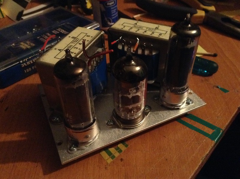
Today I took apart an old Victrola Radiola ca. 1928 and salvaged a working PSU and six RF/AF triodes.

I was able to make a rather well working mono audio amp with the help of some modern silicon wizardry.

https://www.youtube.com/watch?v=Ti6_ULgVZFQ


YT is flagging all audio that is 3rd party now, so let me know if the vids don't work.


Joined
May 4, 2009
Messages
5,443
Points
113
Dude you have way too much time on your hands, get over here and help me out :crackup:

Cool set-up :gj:
 
Joined
Jan 14, 2009
Messages
1,452
Points
83
I heard my name mentioned :D ,

Thanks Sig :) , Nice video and amp too , Valves FTW xD

I have done a few valve things mainly VTTCs and audio amps , Here some ive done .

Stero 50EH5 valve amplifier with EM84 magic eye tubes - YouTube
^^ Built it on my desk to test the magic eye tube circuit , full stereo with 150V B+ , 50 Volt heaters in output tubes , 6.3 Volt heaters for preamp dual triode / magic eye tubes .

KT88 Single ended valve amplifier with EM84 magic eye tubes - YouTube

^^ KT88 Single ended Valve Amp with magic eye tubes and edcore output transformers .

CW audio modulated VTTC Tesla Coil , Sugar plumb - YouTube

^^ A CW audio modulated VTTC using a 811a Valve , the supply is a full wave rectified MOT and 5uF smoothing cap ( 5x 1uF MOC ) , secondary is about 3" high x 2" wide .

Synced triac interrupted VTTC 2 - YouTube

^^ Mini triac interrupted 811a VTTC with 1Mhz secondary ( 2.5" x 2" )

Sync interrupted VTTC Gu81m v2.1 - YouTube

^^ GU81M pentode VVTC ( tube is configured as triode ) , Triac interrupted but for the tube size output was lower than possible .

Half Wave VTTC pulsed Strontium nitrate breakout . - YouTube ( red arcs )
Half wave pulsed VTTC mini coil NaCl electrode . - YouTube ( yellow arcs )

^^ Half wave pulsed mini VTTC with a 811a Valve similar secondary to the audio one .

Triode vacuum tube oscillator thing 2 - YouTube

^^ some simple class C oscillator using a dual preamp triode @ 110V B+ ( 20ma )
 
Joined
Nov 17, 2009
Messages
2,031
Points
83
Hell yes.

One of my other hobbies (too many?) is tubes/thermionic electronics. I have four Dynaco St-70s I'm in the process of restoring, with a Dynaco tube preamp.

All of my headphone amps are thermionic, Sennheiser HD700s and 600s, and a closely guarded stash of NOS 12AX7s and 6BQ5s.

I'm *really* trying to eventually get an amp built with a small mercury arc rectifier I have, and hopefully some thoriated filament power tubes. I haven't had the time, but I *must* eventually have the white and blue glow.
 
Joined
Dec 11, 2011
Messages
4,364
Points
83
I *must* eventually have the white and blue glow.

Haha, hell yes indeed! I love seeing the warm filamentiary glow! Just mind the UVB/C exposure from Hg arc valves. I was a bit disappointed that these triodes that fell into my lap are all odd heater voltages and near-invisible glow, but I'm still glad to have them.

I'd love to do more with these Triodes (have five more), but I don't have a good source for the required heater power, nor grid bias, I don't have any sockets, and I don't have any power resistors or suitable L/C stuff, haha. To do anything serious I'd need an assortment of impedance matching transformers (probably 8 to 2400ohms), inter-stage coupling transformers (1:1, 1:2, 1:4 all @ 2400ohms or so), and variable capacitors/inductors. That's just for basic multi-stage signal amplification too. Would be great to see them being put to good use, but I can't afford the investment to do so. Hell, I don't even have a good speaker for the single triode amp I made, haha.

These are robust and simple but they are a pain to get set up; -16v for the gen purp and -40V for the power triode grid bias points alone is a pain. In the original circuitry the grids were operated at ground potential, with the cathode at +20v ground referenced. This means the entire chasis is above ground potential; not something I approve of. The power triode was set up as a demodulator for AM so -20v put it in cutoff, which worked.

Edit: Updated video for the triode amp:
https://www.youtube.com/watch?v=eM0l1ihVJYY
 
Last edited:
Joined
Dec 11, 2011
Messages
4,364
Points
83
Realized there was an interstage transformer included in the original Radiola 18. Ripped it out and remade my original double triode circuit:
https://www.youtube.com/watch?v=7RQTCzoibtA


Will have to see about getting some four pin sockets, rectifying and filtering the filament lines (to remove hum), and a proper speaker.

It feels good to say that after years of wanting to; I have finally built a fully tube amp.
 
Joined
Jan 14, 2009
Messages
1,452
Points
83
Nice work :D , Ive started a little stereo amp , should give around 1W per channel , the layout isn't the best but I wanted it as small as possible . the only thing that wont be monted on it is the power transformer that will sat beside it .


IMG_0144[1] by TwirlyWhirly555, on Flickr

Build on a small rectangle piece of aluminium
 
Joined
Dec 11, 2011
Messages
4,364
Points
83
Awesome! I'm jealous of you for having a professional looking build underway from "scrap". I'm stuck using an old recycled radioshack plastic abs project box as a mounting surface. I had to order in some four pin bottom mount sockets, but got them cheap domestically on eBay for a change. Yours look way nicer quality than the ones I ordered though.

Where'd ya find the awesome matching plate trafos?

I did some experimenting with negative feedback on my dual triode amp today. While it worked well to suppress noise, the loss in gain was quite noticeable. I guess that's why they didn't really employ it for triodes, but rather tetrodes and pentodes. I also experimented with positive feedback for additional gain, but it was pretty marginal.

Data for others to benefit from: Negative Feedback is easiest to implement via a series resistor between the output valve's audio-pickoff transformer's secondary and the first stage valve's cathode. One leg of the transformer secondary will yield negative feedback, while the other will yield positive feedback. Adding L and or C will affect the frequency response of the NFB loop to shape the output sound.

Negative Feedback + less series resistance = less gain, stronger effect of sound shaping.
Negative Feedback + more series resistance = more gain retained, weaker effect of sound shaping.
Adding a series capacitor forms a high-pass filter in the negative loop, which has a net Low-Pass effect on the sound.
Adding a series inductor forms a low-pass filter in the negative loop, which has a net High-Pass effect on the sound.

Positive feedback loops are more intuitive; more resistance = less additional gain. Series L and C values do not have "inverse of normal" effects on the sound. Depending upon the bias points used and the series resistances chosen positive feedback can introduce a lot of distortion as the tube goes into full conduction and begins to flat-top the signal.

I tried many, many values and ranges of R and C for the NFB loop but couldn't find a sweet point of gain vs low-pass effect that made the output sound better than without the NFB loop. I'm using a higher frequency range small speaker without an enclosure so there is a large inherent high-pass effect. Despite achieving significant results in low-pass filtering I still couldn't balance the sound profile. It would go from "muddy AND tinny" to "thin" with no sweet spot in between. I tried 0-500kOhms linear taper and 1pF to 1uF in x10 increments. The best altered sound I achieved was with a combination of 2.2kOhms + 80nF/47nF (one was better at one song, another for another) and a Positive feedback loop with only a series junkbox mystery inductor somewhere on the order of 100-100uH. The PFB enhanced the bass response while the NFB reduced the treble. Unfortunately nothing seemed to reduce the 60Hz hum (I suspect I'd need a notch filter) or the real high frequencies, above about 7kHz, which was very strange. The low pass effect of the NFB loop should have rolled off everything over the 3dB frequencies but really it just had the effect of a negative Gaussian curve. The result was upper-midrange scooping with linear reduction in bass/treble just due to loss of overall gain. Not sure why that happened.

In the end I decided to stick with the 1920's topology of no feedback and just deal with the frequency response by other means.

I tried briefly to rectify and filter the heater lines to nix the hum but had no luck. Oddly enough the heater wouldn't glow under DC, even though they do from my bench supply. This power supply (for the amp) uses an odd means of grid bias by having the heaters (and consequently the cathodes) at about 23V relative to true ground and then grounding the grids. This makes it difficult to alter without screwing things up. I suspect that due to the large negative bias and zero isolation something ran afoul (hard to believe with 1 diode and 1 cap!) in my wiring. I had rectified and filtered an unused filament line before but it was the 5V line for the 227 tube I'm not using, and that one's heater isn't held so far negative to ground. Plus, there was a layer of isolation because of the impedance matching transformer used between the silicon preamp and the grid of the 226.

I'd certainly consider implementing NFB again if I can get a proper sharp slope 60Hz notch filter figured out.
 
Joined
Dec 17, 2012
Messages
2,081
Points
63
I dont know much about tubes but I can say my dual rectifier guitar amps sounds amazing and has 6 glowing tubes in the back of the head :)
 
Joined
Jan 7, 2007
Messages
6,309
Points
83
From my OLD experience, Mercury vapor rectifier tubes were not considered as arc tubes.
They needed to be preheated to prevent flash back. As I recall, 816 and 866 tubes were most common. Gas filled triodes were likely Thyrotron (SCR) trigger tubes usually filled with H2.
I have no idea what a dual rectifier amplifier could be. My guitar amp I built 45 years ago has a pair of 6L6 output tubes. The glow is only from the filaments.
HMike

SIG -- Grounded grids is a class C amp. Not usually good for audio but 4 811A tubes will give you ~ 800 Watts..
 
Last edited:
Joined
Dec 11, 2011
Messages
4,364
Points
83
I have no idea what a dual rectifier amplifier could be.

Me either. I'm guessing a marketing gimmick; two rectifier tubes for greater B+ current capacity.

SIG -- Grounded grids is a class C amp. Not usually good for audio but 4 811A tubes will give you ~ 800 Watts..

I've scoped all the stages in the original setup and it was definitely operating at class A; output waveform is identical to input waveform for sinusoidal/square tests. I don't have a digital scope to test linearity of spectrum.

I think what they did was use a multiple winding transformer where the center leg of the center-tapped secondary is tied to the rectified and filtered tertiary to create the DC offset. This way the grid is essentially floating at 0V, the heater/cathode winding at 1.5Vac with a -23Vdc offset, and the B+ to Cathode is +23V higher than the B+ to ground.

I'm reusing the power supply, tubes, and interstage transformer only though, so original wiring scheme is moot as far as original grid bias goes - aside from what is done via the cathode as described above.
 
Joined
Dec 17, 2012
Messages
2,081
Points
63
The recto tubes are 6L6s. The tripple rectifier has 3 6L6s. The tripple has more distortion than the dual. Tube amps sound so much better than solid state amps. I can get a picture of the head later.
 
Joined
Jan 14, 2009
Messages
1,452
Points
83
Awesome! I'm jealous of you for having a professional looking build underway from "scrap". I'm stuck using an old recycled radioshack plastic abs project box as a mounting surface. I had to order in some four pin bottom mount sockets, but got them cheap domestically on eBay for a change. Yours look way nicer quality than the ones I ordered though.

Where'd ya find the awesome matching plate trafos?

.

Thanks :D , I just have a lot lying around . I did have to buy some resitors for it but apart from that I had the rest .

The transformers are 4/8 ohm output with a primary ranges from 1Kohm to 8Kohm and are rated for 10 Watts each , they cost £3.99 Each from a UK company and come with a sheet to give the tap ranges , ill look for the site and let ya know .
 
Last edited:
Joined
Dec 17, 2012
Messages
2,081
Points
63
Two 5U4G rectifier tubes, 4 6L6 power tubes, and 4 12AX7 pre-amp tubes.


Mesa makes one hell of an amp for sure.
 
Last edited:
Joined
Dec 11, 2011
Messages
4,364
Points
83
Yep, the additional rectifiers are just to supply more current to the amplifier stages so that they can be driven harder. Without increasing the input voltage you can't draw more current than valve rectifiers are designed for, so compared to low impedance silicon rectifiers they're relatively fixed impedance (i.e. quasi-constant current sources when input voltage remains somewhat stable) devices.


Top