Sigurthr
0
- Joined
- Dec 11, 2011
- Messages
- 4,364
- Points
- 83
Lol, that could have been a nasty surprise! Any blown equipment?


Welcome to Straya
 IMG_0405 219 by TwirlyWhirly555, on Flickr
 IMG_0405 632 by TwirlyWhirly555, on Flickr
My conical secondary for my Siguthr Coil and the 4" sphere topload. The coil still needs its endless count of polyurethane but my drive motor broke on my winding jig on the last turn. Also the first tested MOT at 2100V. Other one I have I can't seem to get more than 6V out with 5V in? No idea what going on but I haven't ruled out a damaged MOT yet.


:wtf: :thinking:
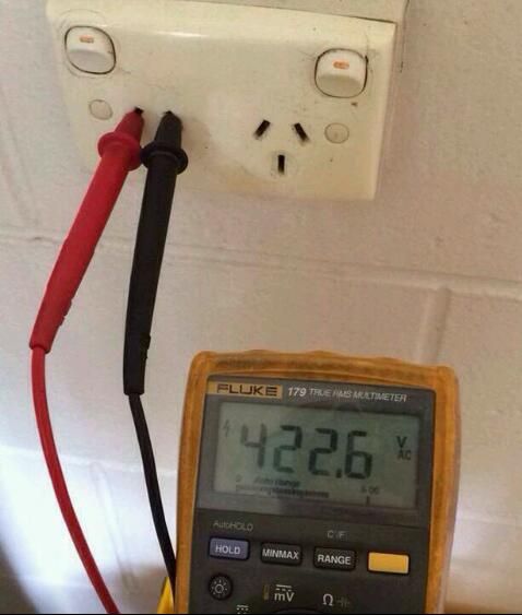
422Vac.. how did you manage that ???
One mistake with that much juice... Wow...
Thanks for the post!


Just to note; I had Speedy use 5Vac from his variac for the tests, which is why the 2100v is calculated and why he read the 89V. Much safer this way.


Sig any way to measure the current on this using the CT from the USSTCC coil and my DMM?
