Welcome to Laser Pointer Forums - discuss green laser pointers, blue laser pointers, and all types of lasers

LPF Donation via Stripe | LPF Donation - Other Methods

Links below open in new window

ArcticMyst Security by Avery

Tesla Coil Build Thread

Joined
Jul 4, 2008
Messages
2,499
Points
113
Is there a circuit diagram I can follow? Any way to see what type or look up mot specs before an oven purchase. I see a bunch of old ones on Craigslist for 5 to 20 bucks a piece.

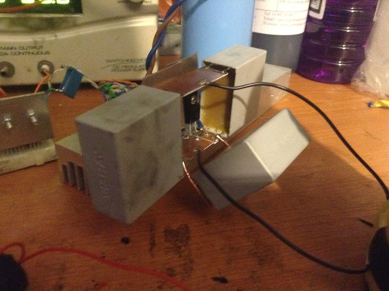
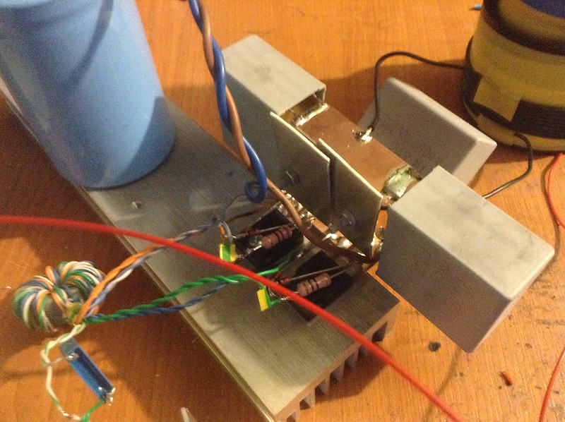
Actually there are plenty of circuit diagrams for MOT XMFR banks.

_-= Uzzors2k =-_ Project Site
Jochen's High Voltage Page : Microwave oven transformers

Great post on 4HV.org about a dual MOT supply with a rotary SPKG.
Forums / Tesla Coils / Help for MOT SGTC - 4hv.org

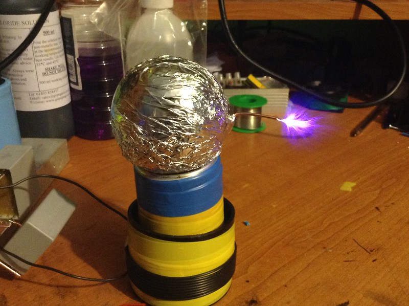
Read and feel itchy looking at the juicy arc pics!! :eg::evil::beer:


hope these links help!
 
Last edited:


Joined
Dec 17, 2012
Messages
2,081
Points
63
So I need to refine 4 microwaves then. 3 mots and 4 mocs. Seems simple enouhh. What is the phasing hes talking about at the end. I hope this railless coil is in tune so I don't have to rebuild anything. Will just need a rsg. I'm going to do the angle grinder one because it's small and cheap. What should I use for electrodes on that? Also should the 12th be run on a varia for bps control?
 
Joined
Jan 14, 2009
Messages
1,452
Points
83
Threw together a mini 950 KHz CW SSTC , half bridge , PLL driver ( GDT was configured for full bridge so I just parallel the 2 sets )

The secondary is about 2" x 3" with 3" topload , 950Khz resonance , 10uF bridge caps , 10uF snubber , 1200uF filtering and average power to the gate drive is 12V @ 400mA

Output is with around 35 Volts supply ( as in picture ) , after 80 volts arc is secondary length , then im scared to go any further xD


IMG_0397[1] by TwirlyWhirly555, on Flickr


IMG_0396[1] by TwirlyWhirly555, on Flickr


IMG_0395[1] by TwirlyWhirly555, on Flickr
 
Last edited:
Joined
Dec 11, 2011
Messages
4,364
Points
83
Excellent work Twirly!

I still have my 1MHz coil waiting for build... parts in the drawer and resonator on the shelf. I'll get around to it eventually.

@Speedy the phasing for a dual-mot is such: the first transformer is wired as normal, the second transformer is wired with the input leads reversed but put in parallel with the first one's input leads. This lets you connect the mot cases together to form a +2.4kV - 0v - -2.4kV output for 4.8kV AC out. The "5mot" bank is just two of these setups wired in parallel for double the output current with the 5th mot being an input current limiter put in series with the "bank". I'm not sure if the 5th is necessary, S_L would know.

I had originally planned to do a MOT TC but when I found out how loud my 7.5/30 TC was when properly adjusted and tuned I decided to move to solid/vacuum state and away from spark gaps.
 
Joined
Dec 17, 2012
Messages
2,081
Points
63
5 would be sweet :) How do I know which wire is which on the primary side?
 
Joined
Dec 11, 2011
Messages
4,364
Points
83
That is where it helps to have either a variac or identical mots.

If the mots are identical just visually reverse the primary connections.

If they are not identical then you would apply very low voltage AC (~10v) from the variac to both mots and use an ac voltmeter to measure the voltage across BOTH mot outputs (from one output to the other) if it reads a low voltage (or zero) then one of the mot inputs needs to be reversed, if it reads about 200V then they are wired correctly.


@Twirly, btw you should AM modulate that and listen to the audio on any household radio. Perhaps even attach a 1/4wave antenna to the breakout.
 
Joined
Dec 17, 2012
Messages
2,081
Points
63
Hopefully a guess based on which side the primary lead comes out will be enough. If not I do have that variac :) The ballast goes on the secondary high voltage side right?

One that first link he posted is a dual mot with a ballast third and the capacitors from the oven. May try that first. The video on there is quite epic.
 
Joined
Jul 4, 2008
Messages
2,499
Points
113
So I need to refine 4 microwaves then. 3 mots and 4 mocs. Seems simple enouhh. What is the phasing hes talking about at the end. I hope this railless coil is in tune so I don't have to rebuild anything. Will just need a rsg. I'm going to do the angle grinder one because it's small and cheap. What should I use for electrodes on that? Also should the 12th be run on a varia for bps control?

A quick search through 4HV forums can show you all about RSPKGs
Having built a couple myself, I would be very careful about using an angle grinder. Some larger grinders will work but many are Asynchronous and that creates another wrinkle in how your caps will charge.
First things first.... before anything happens figure out your tesla coil as it is right now. Test the transformer out.
Small problems can become catastrophic when running high powers. You've got a nice looking coil. I'd hate to see racing secondary arcs from it being out of tune. Racing arcs (can be) a fatal coil condition.
 
Joined
Dec 17, 2012
Messages
2,081
Points
63
Of course! Once this coil is running decent on the NST it will be set aside while I build the Sigurthr coil. I'm just trying to get a list together of the potential expensive components so I can snatch them up if I come across one at a steal. The area I'm in really sucks for second hand cheap things. For example looking on craigslist for microwaves half of the results are RV's and the other half are actual ovens that look like space ships priced at more than I have invested in this coil already.... I need to try a thrift store.
 
Joined
Jul 4, 2008
Messages
2,499
Points
113
Of course! Once this coil is running decent on the NST it will be set aside while I build the Sigurthr coil. I'm just trying to get a list together of the potential expensive components so I can snatch them up if I come across one at a steal. The area I'm in really sucks for second hand cheap things. For example looking on craigslist for microwaves half of the results are RV's and the other half are actual ovens that look like space ships priced at more than I have invested in this coil already.... I need to try a thrift store.

Thrift store or a junk shop.

Microwaves..the older the better. Look for some early 90s or late 80s ones.
Those have got some the beastliest XMFRs you can find. :can:
 
Joined
Dec 11, 2011
Messages
4,364
Points
83
Ballasting is done on primary side as it is much safer and usually works better.

Scrapyards are a good place for old microwaves. Usually it isn't the MOT that has failed. I'm not fond of MOT bank designs that use lots of MOCs (for ballasting or filtering) as I've seen MOCs explode many times. MODs (microwave oven diodes) are ALWAYS handy to have though and are necessary for doublers/triplers/etc.

I think the asynch. wrinkle is only a wrinkle if your MMC voltage rating is not far above your MOT bank output. With 5kV 1A output on a >24kV you'd have to have three AC peaks without a gap discharge before the MMC max voltage is approached. That would be 50mS without a trigger. If he made a 4 electrode RSG at only 1krpm it would trigger every 250uS nominally, that would be 200 missed gap discharges before the MMC voltage could be exceeded. Again, why I think it would be easier to go with a high current but relatively low voltage MOT bank rather than a doubled/tripled HV bank. Finding a synch motor and aligning the electrodes is a bitch.
 
Joined
Dec 17, 2012
Messages
2,081
Points
63
I found some 4ga battery hookup wire in the garage but there's no way I can pump enough heat into it to do any soldering. My original plan was to have 3 10ga wires coming off each of the three series cap strings and then all going to the 4ga then to the gap. Same with the top of the bank to the inner turn. How should I attach this or is there a better way? One needs lava to heat up enough and the other is the delicate cap.
 
Joined
Dec 11, 2011
Messages
4,364
Points
83
One needs lava to heat up enough and the other is the delicate cap.

Lol. Use the 10ga for connections to the thinner stuff. Use mechanical connections to the heavy cable. Remember the nuts and bolts setup my mmc had? That was to connect to 8ga. Same idea. =)
 
Joined
Dec 17, 2012
Messages
2,081
Points
63
This 4ga is ridiculous lol. What about having all the ends of 10ga parallel to the 4 and a hose clamp? Maybe that ground rod clamp I have could be used as this also. What about connecting to the primary? Can't really put any stress on hollow copper tube
 
Joined
Dec 11, 2011
Messages
4,364
Points
83
Most people use a battery clamp or some copper sheeting to connect to the primary.
 
Joined
Jan 14, 2009
Messages
1,452
Points
83
Thanks Sig :D ,

Just did a modulation test , using a Opto isolator to level shift a arduino playing square wave notes to then directly modulate the 4046 by its inhibit pin .

Works pretty well , short run as it heats the bridge and secondary doing it .


Top