Welcome to Laser Pointer Forums - discuss green laser pointers, blue laser pointers, and all types of lasers

LPF Donation via Stripe | LPF Donation - Other Methods

Links below open in new window

ArcticMyst Security by Avery

Tesla Coil Build Thread

Joined
Dec 17, 2012
Messages
2,081
Points
63
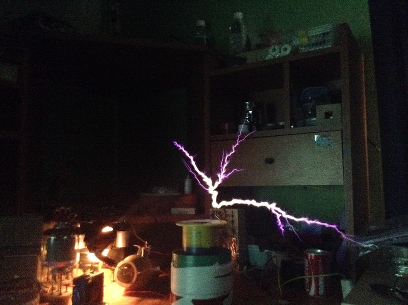
New fun in the high voltage world!

BGS (Big Green Secondary) Gets a nice spun aluminum new hat at 18 inches! This thing is amazing!


Got some work done on Sigurthr's USSTCC.

Soo many parts!


Organized into what part they will become. Interrupter, Bridge, USSTCC


C1 is installed now. Was back-ordered and came today.


GDT


CT


Interrupter! This things is packed tight with components! Essentially the first thing I have ever made on this proto board. Was stressful lol


It works!

Next step on BGS is MMC for the new NST, base, and primary.

Next on the Sigurthr USSTCC is constructing and winding the conical secondary (Yes, conical secondary :) ), primary, and base. Also have a 4" sphere for the topload that needs a break out. Oh and the interrupter is getting a fancy box with some sort of plexi window. I plan on printing out "Sigurthr USSTCC" and pasting in under the window and have the status LED on the interrupter illuminate it :)

Edit: Since this is a laser forum and not a tesla coil forum here is my random relevant laser pic. The new 3.3W 445 in one of Sinners hosts and my snake tank. :)

Spike and Mitch are chillen out in front. Zack you can barley see hiding behind the water tub and that stick.
 
Last edited:


Joined
Dec 11, 2011
Messages
4,364
Points
83
Absolutely awesome work. I'm eagerly following your progress!


Sent from my iPhone using Tapatalk
 
Joined
Jan 14, 2009
Messages
1,452
Points
83
Nice green secondary :D , look forward to seeing it run .

I got a new tube , the GMI-83V which is a pulse tetrode , has a dissipation of 60W ( 20W more than the 811A ) but has a much higher anode voltage of 20kv max ( in 5uS pulse operation ) but in the TC its running way longer pulses .

Im running it from a dual MOT + half wave doubler to give around 7-8Kv on the plate , Trying for longer arcs from the same 6" secondary , but the results are a lot thicker arcs and more branches with strikes at 14" long .


IMG_0368[1] by TwirlyWhirly555, on Flickr
 
Last edited:
Joined
Dec 11, 2011
Messages
4,364
Points
83
Unlike the popular opinion, 5kV isn't a magical threshold for X-ray generation. Research has been done that has proven X-ray bremsstrahlung generation occurs in hard vacuums down to 1.2kV.

The reason external detection of X-rays below 5-8kV isn't possible is due to the shielding effect the glass envelope has.

A general guideline is if you don't see any green glow from XRF then you're okay as long as you're not sitting there staring at the tube. After all, early cathode ray tubes operated at over 30kV and had much thinner envelopes than "modern" tubes, and the phosphors only provided minimal shielding.


Sent from my iPhone using Tapatalk
 
Joined
Dec 17, 2012
Messages
2,081
Points
63
Fixed the toroid to the secondary using some pvc and zip ties.


I like where this is going :)


Boxed the interrupter. I was unable to do my window idea :(


I have 1 question. The fiber light seems to be brighter in CW than in the highest PW and frequency on the other setting. Is this normal?
 
Joined
Dec 11, 2011
Messages
4,364
Points
83
Yup totally normal. Even at 50% duty cycle it's off half the time so it appears half as bright. Pulse width is capped on a inverse linear scale because you run out of bits with the large numbers timing in mS and the counter can only go to ~32.7K. Even with creative coding the capability is limited. This results in approx 50% duty cap at lower frequencies. It's works out well though as above ~30% duty there's no visible change in streamer effects, just heat and average power output.

Excellent work though!! Looks similar to the one I made in terms of layout and box. Keep in mind interference gets right in that plastic like nothing so you'll need to be about ten feet out to get reliable operation at full power.
 
Last edited:
Joined
Dec 17, 2012
Messages
2,081
Points
63
SGTC damn near was completed today.

Trip to lowes for all the parts. Had to return that copper. Says 1/4" but that was ID na it was 3/8" OD.


Base and a part of the primary supports.


Each pipe has holes for zip ties and notches on the top to help align the copper as I lay it down.


Holy zip ties batman!


I hope to never see another zip tie. 88 so far and there is still more to go....


Primary and strike rail. Looking sweet!


Spaced out nicely. Spacing was accomplished after it was wound to make it easier.


Here's my power switch. Wired it up to a standard plug. The female plug will be wires up to the NST only. Fans will turn on when I plug in the IEC cable to the IEC plug I'm adding. That way I can remove all wires and stow them so its easier to move.


Wife is briefed on this little device already but just in case lol


Tossing around ideas of how to organize this. MMC needs to be redesigned anyway. Adding 21 more caps for the new NST. To save on space I will be going vertical so the entire MMC is being hit by the stacked fans.


To Do List:
-Build new MMC
-Bolt down everything
-Shoot wire
-Ground base of secondary and hook up toroid to top of secondary
-Attach secondary to base
-Ground Strike rail
-Build 12V DC voltage system to power high speed fan for proper quenching. (Need help
on this BTW. Have 19V laptop supply and 7812. Not sure what else needs to be in that circuit)
-Make RF ground in backyard
-Fire and tune :)

Optional:
-Sweet ass breakout point
-Grounded strike rod


Speedy78
 
Last edited:

ARG

0
Joined
Feb 27, 2011
Messages
6,772
Points
113
20140315_222925_zpsce7bde52.jpg

That put a giant grin on my face. My first thought was that someone was going to plug it into the wall :p Looks like you have that covered though ;)
 
Joined
Dec 17, 2012
Messages
2,081
Points
63
It definitely is the idiot box. Parts were readily available and cheap so I went that route. Thought about reversing the plugs but the cheapest female plug they had was like 8 bucks and same with the male. They are all fancy and can handle like 600000 amps. Way to much for my needs and outside of my price range.
 

ARG

0
Joined
Feb 27, 2011
Messages
6,772
Points
113
You could make the switch short from neutral to ground and leave live floating, shouldn't be a problem if someone sticks it into the wall then :p
 
Joined
Dec 11, 2011
Messages
4,364
Points
83
-Build 12V DC voltage system to power high speed fan for proper quenching. (Need help
on this BTW. Have 19V laptop supply and 7812. Not sure what else needs to be in that circuit)
Speedy78

You need an input capacitor >40uF and an output capacitor >100uF, and a Heatsink.
 
Joined
Dec 17, 2012
Messages
2,081
Points
63
You could make the switch short from neutral to ground and leave live floating, shouldn't be a problem if someone sticks it into the wall then :p

That's exactly what I will do. Just in case. Would hate for the house to burn down.

You need an input capacitor >40uF and an output capacitor >100uF, and a Heatsink.

OK. How much heat would it be putting out? I have a small heat sink designed for these type of chips . Is that enough?

Also what do the caps do exactly? I see them in the interrupter as well.
 
Joined
Dec 11, 2011
Messages
4,364
Points
83
The caps prevent the 7812 from oscillating and increase the instantaneous power draw capacity on load start up.

The Heatsink requirement depends on the current draw of the load. No idea how much the fans draw.
 

Fiddy

0
Joined
May 22, 2011
Messages
2,726
Points
63
why 12V fans? 110AC are easily do more CFM cause of there higher voltage, also means no step down power supplies.
 
Joined
Dec 17, 2012
Messages
2,081
Points
63
12V 1.2A. This particular fan has about 3 times as much air flow and it's very directive. Perfect for the spark gap.


Top