Welcome to Laser Pointer Forums - discuss green laser pointers, blue laser pointers, and all types of lasers

LPF Donation via Stripe | LPF Donation - Other Methods

Links below open in new window

ArcticMyst Security by Avery

Single digit VFD Clock , 74 Logic Based , DIY

Joined
Jan 14, 2009
Messages
1,452
Points
83
Hey ,

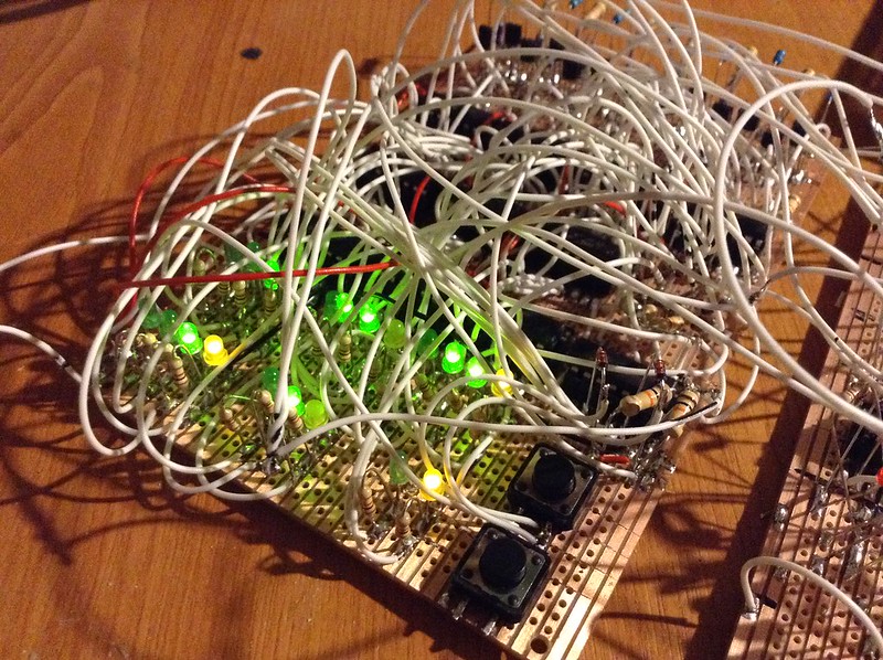
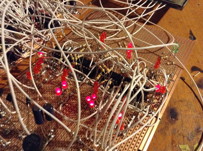
This was a project I did over the last week . It's based on 3 dual BCD counters , 7 Quad AND gate IC's , One BCD-7 Segment driver and 4 4017 decade counters and a few resistors , LED's and 1N1484 Diodes , Transistors . Supply is 2 5Va transforms at 7 and 9 V and one 1.6Va transformer at 22V

Video of it running can be seen here - https://www.youtube.com/watch?v=JDMBcq2oVBk&list=UUvjDVNxRU2DInDMQQw_iYJA

Timing is done from the mains frequency , 50Hz - 100Hz - 10Hz - 1Hz .

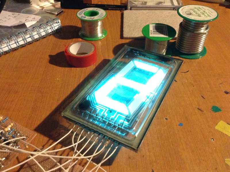
Display is a large VFD driven by 8 ( 1 for grid ) NPN/PNP level shifters at 24 Volts .

AND gates are used along with 16 diodes to select the digit to display with the 4017 doing the timing for when to display time , its currently setup at 48 seconds off and 12 seconds on with it displaying the time twice at 1 second per digit to complete a 60 second cycle .

IMG_0900[1] by TwirlyWhirly555, on Flickr

IMG_0898[1] by TwirlyWhirly555, on Flickr

IMG_0897[1] by TwirlyWhirly555, on Flickr

IMG_0896[1] by TwirlyWhirly555, on Flickr

IMG_0902[1] by TwirlyWhirly555, on Flickr
 
Last edited:


Joined
Dec 11, 2011
Messages
4,364
Points
83
Awesome project! I saw it on YT when you uploaded, but the pics are sweet.

How do you like working with stripboard? I can't stand the stuff, haha. Rat's Nest wiring I don't mind so much, but strip board just gives me headaches.

What's the power section for the VFD like? I've seen small VFDs that run on like 88V, how does the big one compare?

I was wondering what you were using for timing. I assume the 50 -> 100Hz stepup is just via full wave bridge and then using the dc pulses to two cascaded /10 counters, right? You're so lucky to be on 50Hz service. I can't figure out for the life of me an easy way to get 1Hz from 60Hz, haha.
 
Joined
Jan 14, 2009
Messages
1,452
Points
83
Thanks ! : D ,

I quite like using it , I just use a craft knife and a ruler to cut the tracks across the board in rows , most If not all my circuits are made on it , but a low power, small tipped soldering iron is a must on this I think , the wiring was worse than the board xD

There would be a lot less wires if not for all the leds , but they help debug and make a nice visual look to what is actually going on .

The Big VFD has a anode voltage rating of 22-24V . I used a 22V transformer and a 24V regulator to do the supply , grid current is 20mA and each segment is driven at 4mA .

The cathode in the VFD is 5 Volts witch is handy as the logic is 5 volts .

Yeah that's pretty much it 50Hz AC to 100Hz DC where there is a two transistor buffer to give a nice clean 100Hz 5V square wave to then drive the two divide by 10 counters .

You can do it with 60Hz aswell with three ICs but one of them does a odd division .
 
Last edited:
Joined
Dec 11, 2011
Messages
4,364
Points
83
You can do it with 60Hz aswell with three ICs but one of them does a odd division .

At that point you're a short hop away from just using a standard 1Hz time keeping method like a 32768 crystal and a binary counter.

The 60hz decision never made much sense to be because there are no 60Hz 240V countries, and the core material savings you get from using 60Hz instead of 50Hz is totally swamped out and negated by the losses and resultant increased conductor cost of using 120V instead of 240V!

Very interesting that the VFD is such low current and voltage. I would have thought such a supply would be eating tons of power. I recently saw a small 20x4 or 16x2 VFD that ate up a whopping 1A @ 12V.

I've always wanted to make something with a nice 20x4 dot-matrix VFD, but never had the budget for such a project.

I had an old VFD TI calculator when I was young, loved that thing!
 
Joined
Jan 14, 2009
Messages
1,452
Points
83
I looked and it can be done with two IC's , I was going to go with the crystal and the 14 stage binary ripple counter but opted for the 50Hz rout .

You can do it with 60Hz aswell with two 4018 decade counters , feed in 60Hz , first is set to divide by 6 then the second divides by 10 = 1Hz : D

I was surprised at the low anode voltage, it can be driven at higher currents on both the grids and anodes but for this I had no reason to really, Haha yeah some of them displays do like power , but I guess that's because they use boost converters ?

Yeah , the VFD displays can be abit pricy . I wanted to do something like that with a 20x4 and a GPS module for a GPS clock but never got round to it .

Nice ! ive never seen a VFD calculator in person : (
 
Last edited:
Joined
Dec 11, 2011
Messages
4,364
Points
83
I wanted to do something like that with a 20x4 and a GPS module for time and that but never got round to it .

Nice ! ive never seen a VFD calculator in person : (

I'm actually working on a clock project right now, but I'm going the LCD + TCXO RTC route. I had debated going GPS but with reception and power consumption issues I decided against it.

One day I'd like to do a 7segment x 6 nixie clock, but they're so expensive. I think you did one already, didn't you?

You can find them inexpensively on eBay from time to time (VFD Calcs). I really wish I would have saved that old one.
 

phenol

0
Joined
Oct 30, 2007
Messages
533
Points
18
this thing reminds me of my vfd freq counter, but the rats nest wiring i did is on a much much smaller scale so it can count 200MHz with standard cmos chips. I made a small push-pull boost cct with 74hc132 to boost 5v to 20v for the vfd anodes.
 
Joined
Jan 14, 2009
Messages
1,452
Points
83
I'm actually working on a clock project right now, but I'm going the LCD + TCXO RTC route. I had debated going GPS but with reception and power consumption issues I decided against it.

Nice : D , Is the RTC rout easy to do ? I have a few numitron tubes and high current shift registers ( similar to the 595 except open drain inputs ) to do a 6 digit clock .

I haven't used nixi tubes yet , I did do a 6 digit VFD one but never finished it .

Phenol , Thanks , Yeah wiring in mine wasn't critical as the highest speed signal is 100Hz and that's from one IC . The rest is 1Hz at most .
 
Last edited:
Joined
Dec 11, 2011
Messages
4,364
Points
83
Nice : D , Is the RTC rout easy to do ?

On a uC yes, exceptionally easy to do. Analog not so much since most if not all easily available inexpensive RTC modules use I2C for communication. The DS3231 has a 32768Hz output which you could use for analog though, and it is the TCXO type RTC too. I haven't seen any simple XO RTC's with the 32k768 output but again then you really don't need the chip without the digital comm being used, it just serves as an oscillator-on-a-chip. So you could just whip up an XO and proceed from there.

Thanks MarioMaster, I'll check it out!
 
Joined
Jan 14, 2009
Messages
1,452
Points
83
On a uC yes, exceptionally easy to do. Analog not so much since most if not all easily available inexpensive RTC modules use I2C for communication. The DS3231 has a 32768Hz output which you could use for analog though, and it is the TCXO type RTC too. I haven't seen any simple XO RTC's with the 32k768 output but again then you really don't need the chip without the digital comm being used, it just serves as an oscillator-on-a-chip. So you could just whip up an XO and proceed from there.

Thanks MarioMaster, I'll check it out!

Thanks, I had a look and will go down the TCXO IC rout with a arduino , shift registers and numitron tubes .
 
Joined
Dec 11, 2011
Messages
4,364
Points
83
Just keep in mind if you want to use I2C (recommended) you have to stick to an ATmega chip. I found out today you cannot use the ATtiny family of chips even though in the datasheet they say they support I2C as they really don't (software emulation only; and there's no arduino compatible library to carry over the functions needed in the various normal libraries to the emulated version).

If you need any help figuring out what libraries to use just hit me up, I've got it worked out pretty well now.


Top