Welcome to Laser Pointer Forums - discuss green laser pointers, blue laser pointers, and all types of lasers

LPF Donation via Stripe | LPF Donation - Other Methods

Links below open in new window

ArcticMyst Security by Avery

Shower temperature controller

Joined
Jun 22, 2011
Messages
2,431
Points
83
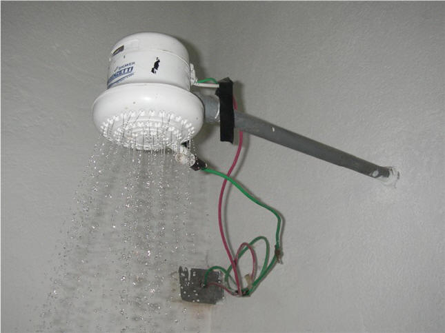
I'm tired of never being able to get the shower temperature exactly right so I decided to build a DIY temperature controller.

I intend to use an Arduino, a temperature sensor (maybe this one) inside the "wet chamber" of the shower to measure water temperature (will need to use some glue or epoxy on those pins to insulate) and an LCD to show water temperature and set temperature. I'm planning on using the PID algorithm on the controller and some capacitive buttons inside the plastic box to avoid shocks.

Now the problem is that I don't have much experience with AC and I don't know the best way to modulate it. I first thought about using PWM on an SSR like this but have been told it won't handle a proper PWM frequency (no idea what a proper frequency would be) and that I should use an SCR or Triac instead because of some sort of phase synchronization issue. I've read up the basics on SCRs and Triacs but I still have no idea how to make them work. All I have found are some dimmer circuits but they all seem analog and not linear at all (I'd like to able to get a linear range from completely off to full power).

I know this is kinda off topic but this forum has some very knowledgeable people and I'm sure someone here will be able to point me in the right direction.

Thanks!


Joined
Sep 12, 2007
Messages
9,399
Points
113
The simplest way to turn PWM into an analog signal (which is a more acceptable input for many devides) is using a low pass filter. Ask teh google

What sort of valves will you be using?
 
Joined
Oct 26, 2007
Messages
5,438
Points
83
Interesting project, but I'd first concentrate on getting your water heater providing consistent temperatures, rather than trying to PID multiple valves.
 
Joined
Feb 1, 2008
Messages
2,894
Points
0
I believe that sensor has a digital value as the feedback to the micro... how much programming experience do you have? I would think you could get faster response times and higher sampling rates from a simple thermistor.

And eh... I don't really see the use of PID implementation here. The water lines in a shower can only move water so fast and temperature can only change as some relatively slow finite rate anyhow.. plus stability over the order of milliseconds is not an issue either..

You could probably add integral compensation to the proportional control if you need super accuracy, but there should be no need for differential reaction times with such a slow system to be controlling.

I don't really understand your control mechanism though... are you using special voltage controlled valves behind your shower wall? Or a motor or two on your "hand" lever?
 
Joined
Jun 22, 2011
Messages
2,431
Points
83
There are no hot/cold valves on most showers here in Brazil, most likely because houses don't need central heating because of the tropical climate. That's probably the reason I couldn't find much useful info on Google.

Here's how it works currently: unheated water from the water company goes to a high capacity reservoir on the roof (2kL or something), from there it goes down a pipe, which has a single "tap style" valve which controls the flow of water. From the tap it goes to a shower head:
IMGP0902.JPG

It has a wet chamber which gets filled with water and has a huge 2.2Ohm wound resistor and from there the water sprinkles down as usual. Above this wet chamber there's a dry chamber which has a mechanical thingy that turns on the resistor whenever the other chamber is full of water. There's also a switch to connect the mains to either the center tap of the resistor (lower resistance, high power) or the end tap (high resistance, low power). It draws 5.5kW - 50A from 110V@60Hz.

My idea involves no plumbing, I'd just leave the shower head on the high power setting and modulate the mains voltage that goes into the heating resistor. I'm not exactly sure PID would be the best choice but most heating control seem to use it so I figured I should do that as well :)

I'm not sure I can use a low pass filter because the shower is designed to take 60Hz AC. I thought about rectifying the mains voltage and PWMing that with a MOSFET but I don't know if it'll damage the resistor.

I have a lot of programming experience but my electronics experience is more limited. I can design and hook up everything except for the part that modulates power to the huge resistor. Might use a thermistor instead, I'll look into it, thanks!

Hope someone can help me figure out the best way to modulate power to the huge resistor :)
 
Last edited:
Joined
Oct 26, 2007
Messages
5,438
Points
83
Ah, you should've explained that you had that kind of setup. It's like those expensive "endless" water heaters that heat up water on the fly like you've go there.

Anyway, what you might try is putting a high-current MOSFET in line with your heating coil and regulate the current with PWM and a controller. Use some sort of temperature sensor in line with the water flow to as feedback (thermistor, or others).

The above shouldn't be too hard to implement. The MOSFET's gate can be triggered from some PWM output on your Arduino and the sensor can be placed in line with the outflow of the heating element. Given the large currents involved here, you may also consider using some opto-isolation and a separate power circuit for the controller. The gate to the MOSFET should also be pulled low (OFF, assuming a low-side configuration), when the controller output is floating (i.e. the Arduino is off). Something like this might work (the relay on the top-right would be replaced with your heating coil).

The more important part in this circuit will be the safety mechanism to ensure that your heating element only turns on when it is supposed to: when the water is actually flowing. I would install something like an electronic flow sensor to ensure that water is flowing before allowing that coil to fire up. Also adding some sort of emergency temperature sensing "fuse" on the rig might be a good last-resort safety measure. Those hot water pump pots employ that in their designs should the pot ever run dry.
 
Joined
Jun 22, 2011
Messages
2,431
Points
83
That sounds like a good simple plan but won't I have to rectify the mains AC before feeding it to the MOSFET? The heater coil is designed for AC, do you figure powering it with DC will make it fail sooner?
 
Joined
Sep 12, 2007
Messages
9,399
Points
113
Yes, it would need to be rectified if you were to use a single MOSFET, but insulated ceramic heating elements (and I assume yours is) don't care if they're fed AC or DC.

A solid state relay would be the easiest option, but you might be able to get away with using a triac instead.
 
Joined
Oct 26, 2007
Messages
5,438
Points
83
Ah, I had forgotten about the rectification. Yeah, as suggested, an SSR or triac would work. A SSR can be relatively expensive at higher current ratings. Triacs are a bit cheaper, but you should ensure that it's snubberless (i.e. they only switch only when the waveform crosses zero volts) so it doesn't burn itself out. Also ensure that the triacs are always modulated (PWMed), because they have steady-state current limitations, even if they can handle higher peak currents. You'll also need to include your own opto-isolator.
 

Things

0
Joined
May 1, 2007
Messages
7,517
Points
0
SSR's = triacs, basically.

A TRIAC is what you want to use, preferably with a zero crossing detector to lighten it's load a little. What you're trying to achieve is called a "chopper", which as it's name implies, chops up the power at certain times in the sine wave to give you a varying output. All modern light dimmers work in this way, heating elements are basically identical to incandescent lights electrically.

Using PWM is pointless, as your AC sinewave is only 50/60hz, so would only need to be chopped a few times per cycle, and heating elements generally have enough thermal mass to deal with being off for slightly longer periods of time. This method is more efficient because you're not actually doing any regulation yourself. The AC line is already swinging between 0 and 120V, so you just have to turn on the heating element at the right time on the wave and you have adjustable power, with only switching losses in the TRIAC.

http://wiki.dxarts.washington.edu/groups/general/wiki/4dd69/AC_Dimmer_Circuit.html

http://arduino.cc/playground/Code/ACPhaseControl

Choose a suitable TRIAC and you're set.

PS the wiring on that thing looks bodgy as hell! You'd probably go to jail for that here :p
 
Last edited:
Joined
Jun 22, 2011
Messages
2,431
Points
83
Cool, that's exactly what I was looking for!

That's not my shower, just some random pic I found on google. Mine is (slightly) better XD
 
Last edited:


Top