- Joined
- Aug 16, 2013
- Messages
- 971
- Points
- 43
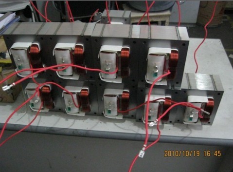
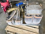
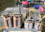
The old Sanyo radar range XMFRs are very heavy and massively overbuilt. this is good. It means they can be run above spec (~ +50%) without having much in the way of issues. The smaller XMFRs aren't very durable.
Benm is also quite correct here as well. So I'll second his opinion as well. :beer:
I'd also like to add that the large transformers will start smoking long after your house wiring starts burning.
This is why I explained about the shunts actually not being very helpful in controlling current draw,
but a single (radar range) mot without a secondary cap will draw about 35-40A at 120Vac.
This is also why the 2000VAC rated cap in the secondary is required.
Those linked videos were intense. Hell of an arc. I don't think Best Buy's geek squad would take that mother board back.
-I actually do have an array of 240v incandescent light bulbs I was using to bleed down capacitors benm, so that's not a bad idea.
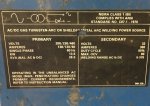
Can you expand upon this "radar range" transformer? Is this a special application XMFR or Class.
Scenario: I have a large MOT. Input is for the north American voltage of 120VAC. I have at my disposal a 240v 30A outlet with a 7.8kVA variac. It's it possible to over drive the mot that 50%?
Correct me if I am wrong but the difference between a microwave for the United States vs one from Australia the number of turns on the primary?
What would happen if I ramped that F****R up to 240Vac? Let's assume the core was ground. Would the insulation break down between the windings and core?
This is all precursor research for possibly building a large large RGTC in the future.