

RayJay
0
- Joined
- May 2, 2014
- Messages
- 344
- Points
- 0
Hey everyone,
I got in a package today!
I'll let the photo's do the talking..
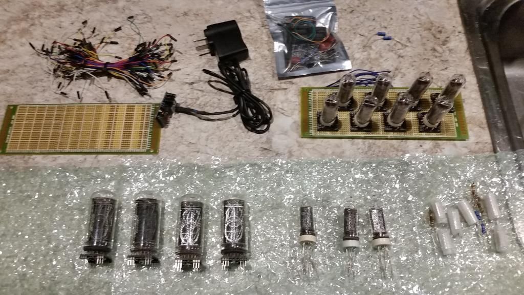
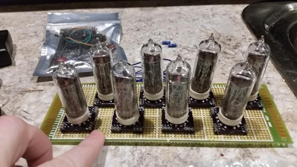
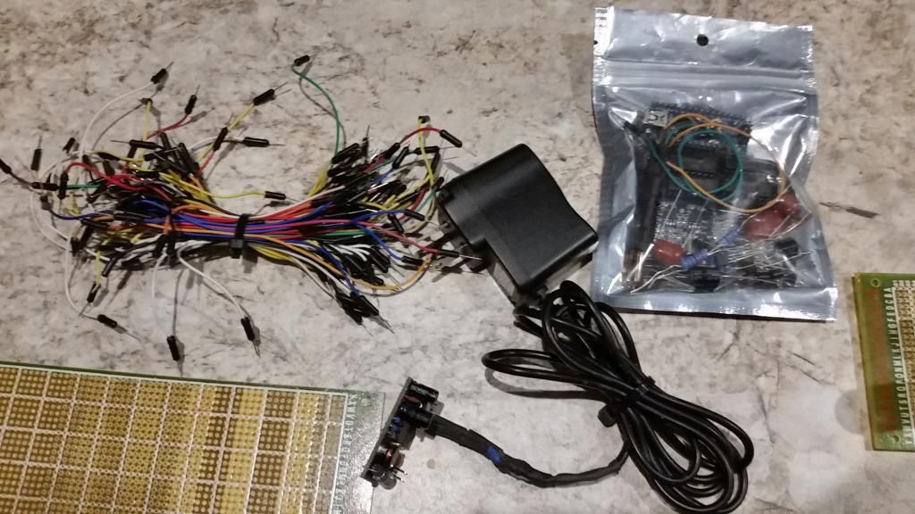
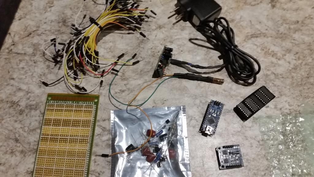
Things included are..
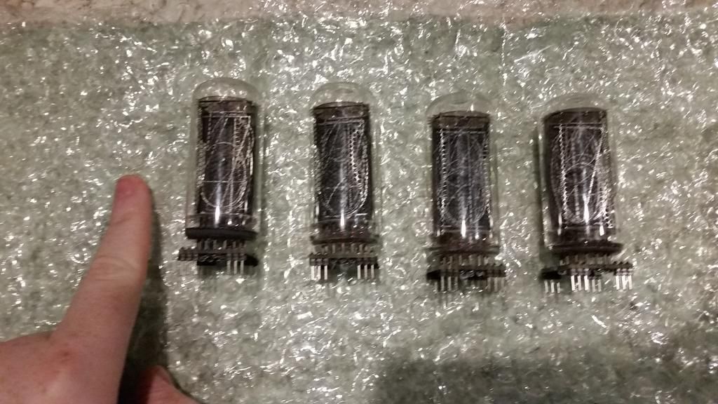
4 x IN-18
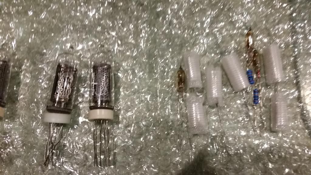
2 x IN-14
4 x IN-19A
5 x IN-19B
9 x colon markers
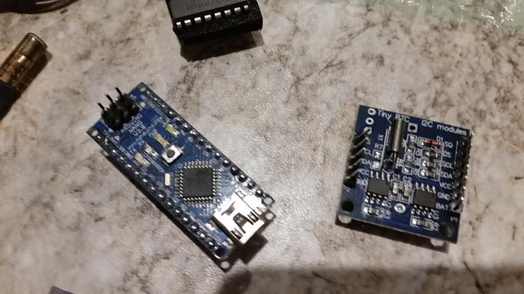
1 x Arduino Nano V3.0
1 x Tiny RTC 12C Module
2 x Proto Boards
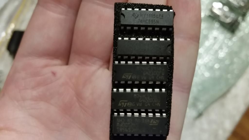
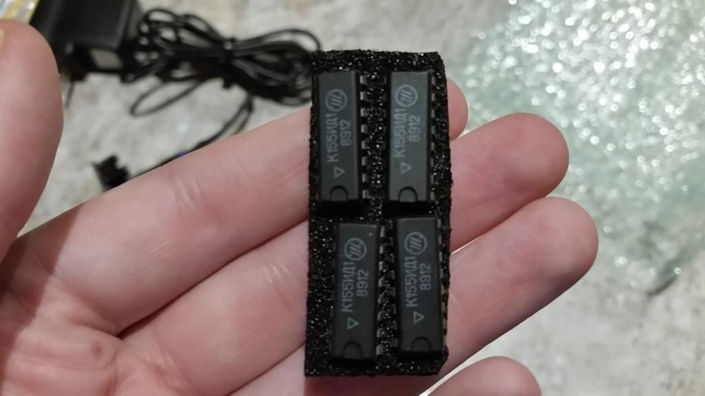
And a TON of wires, diodes, etc that I have no idea what they are/do?!
I also think there is some type of sensor (temp maybe?) in the middle of the second last photo?
So, I have been told that I have "most of the parts" to make a clock..
I know I have more than enough tubes!! (although I was expecting 6 IN-18's instead of 4..but who's complaining!)
The thing is... I have no idea what I am looking at here? And have NO idea what to do?? Any tips? Fiddy? I know you have made a few..
Are there any schematic's or tutorials online? I was just going to buy a kit from PVElectronics but I thought if I already have everything here i'd try myself first..
Thanks guys!
I got in a package today!
I'll let the photo's do the talking..
Things included are..
4 x IN-18
2 x IN-14
4 x IN-19A
5 x IN-19B
9 x colon markers
1 x Arduino Nano V3.0
1 x Tiny RTC 12C Module
2 x Proto Boards
And a TON of wires, diodes, etc that I have no idea what they are/do?!
I also think there is some type of sensor (temp maybe?) in the middle of the second last photo?
So, I have been told that I have "most of the parts" to make a clock..
I know I have more than enough tubes!! (although I was expecting 6 IN-18's instead of 4..but who's complaining!)
The thing is... I have no idea what I am looking at here? And have NO idea what to do?? Any tips? Fiddy? I know you have made a few..
Are there any schematic's or tutorials online? I was just going to buy a kit from PVElectronics but I thought if I already have everything here i'd try myself first..
Thanks guys!
Last edited:


 )
)