Welcome to Laser Pointer Forums - discuss green laser pointers, blue laser pointers, and all types of lasers

LPF Donation via Stripe | LPF Donation - Other Methods

Links below open in new window

ArcticMyst Security by Avery

Need some help with my laser sound transmitter

lazer

0
Joined
Dec 21, 2008
Messages
361
Points
0
I built a transmitter that uses a small 5mw laser to transfer sounds and music to a receiver. I am having problems with static though. I get alot of background static. Does anyone know of a circuit which could counteract all the static. Maybe some kind of filter type circuit? I dont know what you would call it. Do you guys think an op amp would help?

I also have another minor problem, the transmitter input volume has to be really loud, as in maxed out. I found that is I give more power to the receiver it helps a little but not much. Is there a way I could amplify the input to the transmitter to make the receiver's output louder?

The reciever is just a small photocell hooked to a 9v battery with a mono plug.
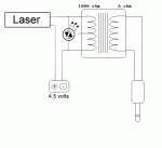
This is the transmitter wiring diagram:
 

Attachments

  • laser_transmitter.gif
    laser_transmitter.gif
    8.2 KB · Views: 859
Last edited:


Joined
Aug 20, 2008
Messages
709
Points
0
It depends on how "loud" the background noise is relative to your desired signal. If the background noise quieter, a simple squelch circuit might work. If it is the same "loudness", you're probably looking into more complicated stuff like T or Pi filters(essentially a network of chokes and capacitors).
 
Last edited:

lazer

0
Joined
Dec 21, 2008
Messages
361
Points
0
The background noise is quieter than the desired sound. Do I need a dual squelch circuit or a single?
 
Last edited:
Joined
Aug 20, 2008
Messages
709
Points
0
If that's the case, a squelch control should work. In case you don't know, a squelch is simply a device that "blocks" off anything under a certain dB; as long as your desired signal is "louder", it should make it through.

You can probably get by with a single squelch.
 
Last edited:
Joined
Oct 24, 2009
Messages
2,738
Points
63
Here goes...

First of all your optical receiver will pick up 60 Hz "hum" from every ac light in the room.

If you are "transmitting" in analog, then every slight variation in ambient light will be received by your "pickup" device.

Now if you were to use DIGITAL signals, you can "transmit" with a TTL modulated laser and DECODE your signal at the other end.

Digital will ignore ambient light fluctuations, thus you can get MP3 (not quite CD) quality from such a device, and "broadcast" in stereo as well.

However I do sincerely admire the ambition and thought you are putting into this.!!
 
Last edited:

lazer

0
Joined
Dec 21, 2008
Messages
361
Points
0
Here goes...

First of all your optical receiver will pick up 60 Hz "hum" from every ac light in the room.

If you are "transmitting" in analog, then every slight variation in ambient light will be received by your "pickup" device.

Now if you were to use DIGITAL signals, you can "transmit" with a TTL modulated laser and DECODE your signal at the other end.

Digital will ignore ambient light fluctuations, thus you can get MP3 (not quite CD) quality from such a device, and "broadcast" in stereo as well.

However I do sincerely admire the ambition and thought you are putting into this.!!

That would explain why there is so much background noise. Do you know where I might find a schematic for a digital circuit? It would be great if I could get mp3 quality sound from this thing. Im just doing it for fun :) got board and for some reason wanted to build this.
 
Last edited:

lazer

0
Joined
Dec 21, 2008
Messages
361
Points
0
If that's the case, a squelch control should work. In case you don't know, a squelch is simply a device that "blocks" off anything under a certain dB; as long as your desired signal is "louder", it should make it through.

You can probably get by with a single squelch.


I'll give the squelch a try. I think it may wind up cutting out some of my sounds that I am transmitting because at certain point the static overwhelms the sound almost entirely. I think it would help anyways though.
 
Joined
Oct 24, 2009
Messages
2,738
Points
63
Try Google searching "digital photo receiver" or "decoder" and see what you can find.

You can hack open an old CD burner with the fiber optic link (Phillips made these, and they were expensive trash, the product was obsoleted in a year, so surplus parts have to be out there)
 

lazer

0
Joined
Dec 21, 2008
Messages
361
Points
0
Just did a search but all i get is a bunch of digital picture frames and linux coding.
 
Joined
May 31, 2009
Messages
3,239
Points
63
Ok.. just a stab in the dark.. really don't know if this is gonna work, but can you measure the output signal without the laser shinning on it? if so, you can add a diode which will cut the noise out from ambient light which would be the threshold, meaning if the ambient light gives around 0.5v for example you could put in a diode which would bring the threshold voltage to (for example) 0.6v which would cut out the noise. Then once the laser is shone on it, it cuts the ambient "noise" and only plays the signal of the received lasers...

My logic

ambient light - diode = 0

laser output + ambient light - diode = laser output

get it? I don't know if a diode is the best idea... maybe a pot would work better with a cap in parallel.. not sure you can test it out.. would only cost like $2 in parts.. if that!
 

lazer

0
Joined
Dec 21, 2008
Messages
361
Points
0
any idea what size capacitor I would need maybe something small like a 0.1uf?
 

HIMNL9

0
Joined
May 26, 2009
Messages
5,318
Points
0
Can i suggest you to use a fixed frequency for drive the laser pulsed, and then modulate it ?

So, at the receiver side, you can build easily a circuit that filter off all the rest, except the transmission frequency, and then demodulate it, taking away at least 90% of the noise and disturbing signals .....

Cause the voice is mainly in the range of 300hz / 3Khz (this is the limitation of phone lines, as example) ..... you can considerate a good bandwidth if you go from 50 Hz to 5 / 6 KHz ..... so you can use a 50 KHz (100 KHz is better, anyway) modulation for the porting wave, then modulate it in amplitude (practically, you realize an AM comlink, just using a light beam instead an RF signal .....) ..... and at the receiver side, make a filter that pass 50 (or 100) KHz, excluding all the rest, then demodulate the 100 KHz (diode and capacitor is enough) and get just the signal carried from the porting wave .....

Just an idea ..... :)
 

HIMNL9

0
Joined
May 26, 2009
Messages
5,318
Points
0
There's different ways for do that, so i don't know what you prefer ..... you can just use a pwm driver for feed the diode, and modulate the amplitude of the output with the audio signal, as example ..... or give a fixed frequency to the LD, and modulate it with a transistor (like, a pnp with a low value resistor in parallel to the LD, not an elegant system and sure not hi-fi, but it works) ..... or use a dedicated IC for this ..... or a pair of op-amps and a pair of mosfet in variable curren source configuration, and modulate the input with your audio signal ..... or use a led driver for the LD that have a "dim" input, and then modulate the dim input ..... or use an op-amp as multiplier for the two signals, carrier and modulation, and then amplify the output til the level that you need for the LD ..... or use an L200 or also a LM317 as regulator, feeded from a 50 KHz power oscillator, and modulate the output with a transistor on the adj pin ..... there's so much ways for do this, that i'm undecided what to say you .....

In the past, i've tried something similar, using just transistors, as example (30 years ago, we don't had specific ICs, LOL), using a classic astable vibrator with a power output transistor for feed the IR led (at these times, not so easy to get laser diodes, but there was a lot of high power IR leds with lenses assemblies, for gate safety switches and safety / anti-thieves barriers, sold as used / salvaged in electronic fairs :p), with another transistor in parallel to the led for steal current from it when modulated ..... it was a crap circuit, working approximatively at 20 KHz, and with a lot of defects, but, hell, it was the first trial of a 17 yo crazy boy (me, LOL) and worked, LOL

Do you want to just test voice transmission for fun, or do you need it for a stable link for high quality transmission ? ..... keep in mind that, more you want stability and reliability, more the circuit become complex .....
 

lazer

0
Joined
Dec 21, 2008
Messages
361
Points
0
Quote: a pair of op-amps and a pair of mosfet in variable curren source configuration, and modulate the input with your audio signal

Can you make a circuit diagram for this? Ive built a couple op amp circuits before I just have never added mosfets into one before.


Top