Welcome to Laser Pointer Forums - discuss green laser pointers, blue laser pointers, and all types of lasers

LPF Donation via Stripe | LPF Donation - Other Methods

Links below open in new window

ArcticMyst Security by Avery

LM324 voltage input

Zeebit

0
Joined
Aug 27, 2012
Messages
1,110
Points
0
Hey guys.

I need help figuring out the pinout of an LM324 IC. I am still a bit of a noob with electronics. I will be using this chip for an audio mixer and it will be powered by SMPS from a pc.

images


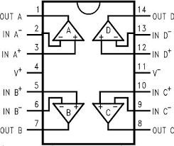
Is it correct that I hook up pin 4 to a positive rail and pin 11 to the PSU ground?


Things

0
Joined
May 1, 2007
Messages
7,517
Points
0
Yep, that's correct. Reason it's marked as V- is because it can also be used on a split rail supply, so the "negative" rail doesn't necessarily have to be at ground potential.
 
Last edited:
Joined
Oct 26, 2007
Messages
5,438
Points
83
Your PSU is a single-rail power supply, i.e. it only goes from ground V_psuGnd = 0V to some positive voltage V_psuPwr = 5V or 12V. That op amp, on the other hand, is a dual-supply op-amp; it wants a +/-V for powering it.

You can use the dual-rail op-amp with your single-rail power supply by treating the PSU ground V_psuGnd as the op-amp negative rail -V, and the PSU positive voltage rail V_psuPwr as the positive rail +V. The important thing in that configuration is that you need to provide a new signal ground, for your input and output signals at V_signalGnd = (V_psuPwr - V_psuGnd) / 2.

To create that V_signalGnd reference, you need to create a virtual ground circuit. You should read over some of the virtual ground circuits here and see what you want to build. Then whatever connection you're making to other electronics, you use the virtual ground as your ground reference, rather than your PSU ground, which serves as your negative rail.
 

Zeebit

0
Joined
Aug 27, 2012
Messages
1,110
Points
0
Thanks guys! It all makes sense now. I once built linear 12v split rail psu but I lost it.
 
Joined
Oct 26, 2007
Messages
5,438
Points
83
Switched mode power supplies such as the PSU you're using are pretty noisy, which can affect your amplifiers. If you're going to build a circuit for audio applications, you should consider building a "clean" power supply so that the signal isn't affected by noise from the PSU.

A decent adjustable voltage regulation circuit can be found in figure 1 of this datasheet for the LM317.

The parts for such a voltage regulator circuit are pretty cheap, and it'll remove a lot of the noise that the PSU and mains power might cause. I would also add a 1000uF electrolytic capacitor before C1, a 10uF capacitor in C_adj, and a 1uF for C_o. Remember that both electrolytic and tantalum capacitors are polarized, but that the electrolytics label the negative (-) pole, whereas the tantalum capacitors label the positive pole (+). Use a 2k pot for R2 if you're using a 12V supply (or calculate from the equation under the figure).

You would then put the virtual ground circuit and the op-amp circuit after the above voltage regulator.
 
Last edited:

Zeebit

0
Joined
Aug 27, 2012
Messages
1,110
Points
0
All stages of my amp (mixer, preamp and tone control, vi meter driver, equalizer and main amp) are gonna be using 12v. Main amp is 2x19W output.

Will the LM317 still be able to filter out some noise?
 
Joined
Sep 20, 2008
Messages
17,622
Points
113
It's not the LM317 itself that will filter noise... It is the associated
support/filtering circuitry that does that. In audio systems the biggest
noise to get rid of is the 60 cycle AC noise that needs be filtered first.

If you power directly from batteries then you have gotten rid of the
60Hz AC problem.


Jerry
 
Joined
Oct 26, 2007
Messages
5,438
Points
83
Lasersbee is right, the LM317 is just a component in that entire circuit; the circuit as a whole needs to be considered. The LM317 is a voltage regulator that regulates the input voltage to a specific output voltage. Combined with the capacitors, it will go a long way in blocking substantial amounts of noise coming from the input. You can see how the capacitors, C_out and C_adj in the schematic, help to block out additional noise in these oscilloscope shots.

Overall, the complete circuit linked to above is a pretty decent power supply filtering circuit, and a good first step to take because it's so cheap to construct. You an even buy PCBs or kits on eBay; they work on both DC and AC inputs. There are dual-power supply versions on there as well. Those are just examples; I would see what is available and if the components are high(er) quality before buying.

You'll need the filtered power for all stages of the audio chain so that the signal remains clean throughout. Shielding the electronics will help too, so find some metal boxes to put your project in when you're done. Ultimately, you should build/use the power supply filtering circuit above just as a first measure, and if it's lacking you can move onto better circuits.


Top