LaZeRz
0
- Joined
- Feb 19, 2011
- Messages
- 2,549
- Points
- 63
I'm still looking around for a large 2000w or so microwave to pull the MOT and capacitor out of. Just need one more cap to get some resonance going on ")
Last edited:


Buy and harvest one
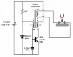
For my first HV project I wired a flyback from a computer monitor to get some arcs using the simplest circuit I could find, which was this:
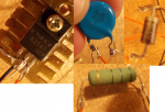
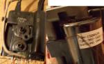
I harvested all the components from the monitor PCB, googling the datasheets to find the descriptions that fitted best what the guy from the video said. I attached pictures of the circuit and the components and adapted the video's schematics to fit my components.
Finding the HV- was easy. I also found 2 coils, one of them connected to 4 pins and the other one connected to 3 pins. Couldn't figure out which one was the primary and which one was the feedback coil, much less which pins to use, so I just tried a *lot* of different wirings.
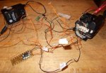
Most of them didn't work. Some that worked "whined" a lot, arced only 1mm and heated the transistor very quickly. Three wirings got me a pretty stable 1cm arc with lower noise and lower transistor heat. Then I tried to switch the primary and feedback coils and got a 2cm arc but it only worked twice, the transistor got very hot and it wouldn't arc anymore, so I went back to the one that got the 1cm stable arc. It worked, so I tried to make a small jacob's ladder and it just wouldn't work anymore - no whine, no arc and a lot of transistor heat. All stable wirings stopped whining and arcing. The 1mm ones still whine and arc, but slightly less.
Did I fry something? Is there anything I can do to fix it?
, i tryed a sigle transistor desing once could never get it to work well . moved over to a ZVS and its great i built mine for 10 pounds and i have enough parts to make 3 more . Using IRF540N Fets i can push 40 volts into ZVS but with heat generation in mosfets but that gives 7" Arcs , but at 30 Volts in i get no heat what so ever and get 4-5" Arcs from flyback . 
Yeah check the resistance between the collector and the emitter, if it is low (<100k) it is probably busted.
Too few primary turns and the impedance of the primary inductor drops and you start pushing a lot of current through the transistor. Too many turns and you limit current by overdoing the impedance, and also increases leakage inductance, which eats away power.
As for reversing the feedback phasing I don't know if it would have any real effect in this circuit, or did you mean to switched which coils you were using for primary and feedback? A common setup for feedback from a flyback is a 5+5 turn primary where the center is tapped and provides feedback.
My best suggestion? Contact Jared (LeQuack) about flyback help... he makes some REAL mean flyback drivers... I have three of his, each with a different topology! Two are half bridges and one is a resonant single transistor build. The resonant single is basically an adjustable frequency 555 timer in astable oscillator mode driving an IRFP450 MOSFET at the tank circuit's resonant frequency. Primary cap in parallel with primary winding and you turn a pot adjust frequency and find the resonant point. Simple circuit, elegantly designed, and very strong. I get long hot arcs of quite high voltage from it, even powering from only 12v. It will even run as low as 5V, but the MOSFET only gets in to the linear region and losses/heat is signifigant.
If you want to put some parts in to it... a center-tap-feedback half bridge of IRFP260s driven by a GDT with mosfet drive chips is the way to go! You'll likely be able to burn out the transformer if you punch enough current through it.