- Joined
- Jan 14, 2009
- Messages
- 1,452
- Points
- 83
Hey
Thought I make a thread on my 6 digit VFD clock that ive started to build") I did post a thread of my led version but this one will be more of the building processes as there will be a case and that too I hope .
I did post a thread of my led version but this one will be more of the building processes as there will be a case and that too I hope .
The logic side of it is 74 series ICs with each 2 digits driven with a dual BCD counter and 2 BCD to 7 Segment drivers . AND gates are used to make the digits reset at the correct time 24 . 60 . 60
1 Second pulse ( 1 Hz ) is produced from rectified mains divided by 10 twice to keep track of the time .
there are a total of 50 level shifter sets each one consisting of 4 resistors and 1 NPN / PNP transistor pair . the level shifters are used to convert the 5 volt logic levels from the segment drivers to 30 to drive the displays .
Each segment of the VFD display sinks 100 ma of current @ 30 Volts , the supply is 35 volts , ( the 5 volt drop is over the resistor that controls segment current ) .
In the pictures I have 8 level shifters setup 7 for the segments and 1 for the grid to reduce wear on the VFD displays the 6 displays will be pulsed on and off one after the other at 200 Hz or so , so that they are not running at 100% duty cycle .
I hope to update this as I go , things I have to do are -
add the other 40 level shifters and wire up the displays , build a 35 volt , 5 volt , 3.15 volt DC supplies and make the case .
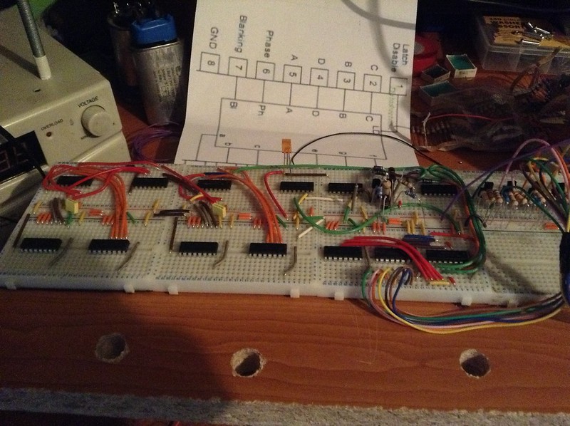
IMG_0440 by TwirlyWhirly555, on Flickr
Logic side of it .
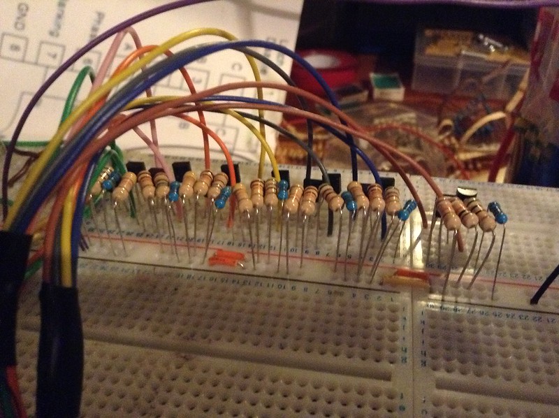
IMG_0443 by TwirlyWhirly555, on Flickr
Level shifters .
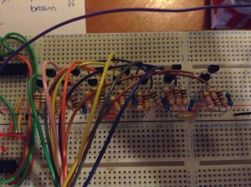
IMG_0444 by TwirlyWhirly555, on Flickr
IMG_0445 by TwirlyWhirly555, on Flickr

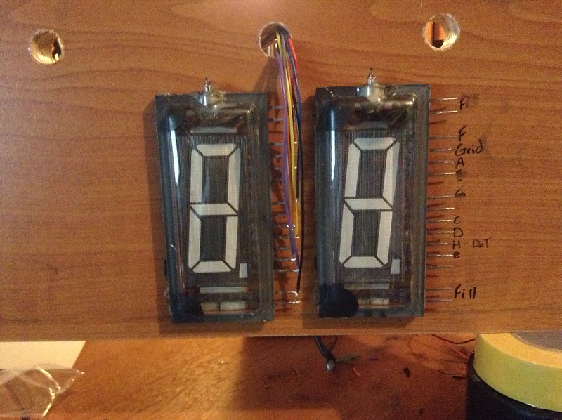
IMG_0446 by TwirlyWhirly555, on Flickr
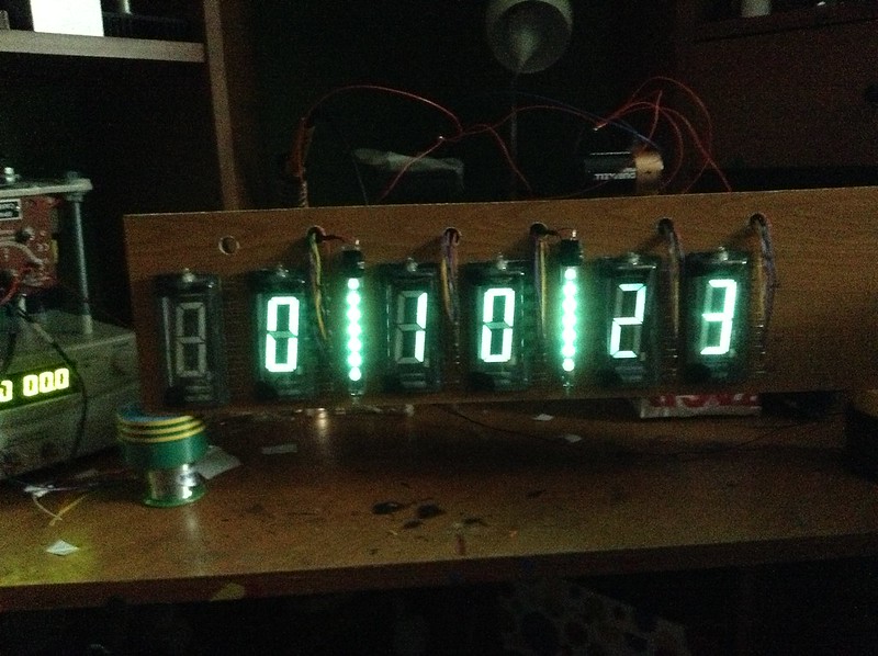
Displays and full size idea .
Thought I make a thread on my 6 digit VFD clock that ive started to build
I did post a thread of my led version but this one will be more of the building processes as there will be a case and that too I hope . The logic side of it is 74 series ICs with each 2 digits driven with a dual BCD counter and 2 BCD to 7 Segment drivers . AND gates are used to make the digits reset at the correct time 24 . 60 . 60
1 Second pulse ( 1 Hz ) is produced from rectified mains divided by 10 twice to keep track of the time .
there are a total of 50 level shifter sets each one consisting of 4 resistors and 1 NPN / PNP transistor pair . the level shifters are used to convert the 5 volt logic levels from the segment drivers to 30 to drive the displays .
Each segment of the VFD display sinks 100 ma of current @ 30 Volts , the supply is 35 volts , ( the 5 volt drop is over the resistor that controls segment current ) .
In the pictures I have 8 level shifters setup 7 for the segments and 1 for the grid to reduce wear on the VFD displays the 6 displays will be pulsed on and off one after the other at 200 Hz or so , so that they are not running at 100% duty cycle .
I hope to update this as I go , things I have to do are -
add the other 40 level shifters and wire up the displays , build a 35 volt , 5 volt , 3.15 volt DC supplies and make the case .
IMG_0440 by TwirlyWhirly555, on Flickr
Logic side of it .
IMG_0443 by TwirlyWhirly555, on Flickr
Level shifters .
IMG_0444 by TwirlyWhirly555, on Flickr
IMG_0445 by TwirlyWhirly555, on Flickr
IMG_0446 by TwirlyWhirly555, on Flickr
Displays and full size idea .