jamilm9
0
- Joined
- Jan 12, 2008
- Messages
- 1,864
- Points
- 0
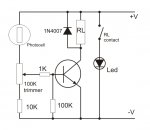
I was wondering if anyone could help me with this schematic. Pretty much when a light (or laser) is shone into the photo-cell then the relay switches and the leds turn OFF. Otherwise they are ON I created this schematic myself and was wondering if anyone could check it over and make sure it makes sense. Thanks


 . So i made a new schematic. This should make the light turn on when there is not laser in the photo cell. Could you please tell me if this will work. Thank You.