i am going to build a guitar effects pedal, i have found the site to buy peices off and a good schematic plan. the only problem is i can understand things like, where to atach the earth and more importantly, where do the '+' & '-' contacts atach.
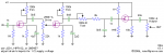
and, when you look closely at the plan, you will see, 250k a-drive, near a switch. is this a pot or resistor or even just the whole switch.
at the in and outouts there are numbers, 1n and 22n, what does this mean?
and finaly, at the output, why does it point to a resistor.
thanks dudes.
and, when you look closely at the plan, you will see, 250k a-drive, near a switch. is this a pot or resistor or even just the whole switch.
at the in and outouts there are numbers, 1n and 22n, what does this mean?
and finaly, at the output, why does it point to a resistor.
thanks dudes.