- Joined
- Nov 2, 2007
- Messages
- 19
- Points
- 0
Hi,
I recently made a DDR pad for use with my computer, and I was planning on putting LED's in the arrow wells for step-on-light-up effect. My first thought was to just put the ground straight to the LED and then run the + wire straight through the contacts that signal the controller. However, that would be putting 12v through the controller as well. Would there be any way I could perhaps put a resistor on it, or something else (I'm not too electric savvy), to keep that 12v from running to the controller?
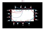
A drawing of an arrow well will be attached, and I will explain the LED route I was thinking about taking.
The 12v + wire would be running through the + arrow well wire, leaving the - arrow well wire for the LED, and the 12v - wire would be connected straight to the LED, once the arrow was stepped on, it would connect the + and - arrow well wire, completing the circuit for the LED and controller.
If there is any way I can do this without running 12v into the controller, I would love for someone to explain it.
Thanks.
I recently made a DDR pad for use with my computer, and I was planning on putting LED's in the arrow wells for step-on-light-up effect. My first thought was to just put the ground straight to the LED and then run the + wire straight through the contacts that signal the controller. However, that would be putting 12v through the controller as well. Would there be any way I could perhaps put a resistor on it, or something else (I'm not too electric savvy), to keep that 12v from running to the controller?
A drawing of an arrow well will be attached, and I will explain the LED route I was thinking about taking.
The 12v + wire would be running through the + arrow well wire, leaving the - arrow well wire for the LED, and the 12v - wire would be connected straight to the LED, once the arrow was stepped on, it would connect the + and - arrow well wire, completing the circuit for the LED and controller.
If there is any way I can do this without running 12v into the controller, I would love for someone to explain it.
Thanks.