D
Deleted member 8178
Guest
Some of you might remember my LED Ball I made a few years ago... It had three LEDs and two axes. Now I've made another one with three axes!
YouTube - Spinning RGB LED Ball II
It was very hard to build! I has a lot of problems with the power transfer and failed may times before I got everything working smoothly. Now it runs like a dream.
I made it all from very simple materials like wood, VCR-parts, fans, junk, antenna tubes and a lot of solder!
Total of 9 slip-contacts, not including the motors!
The current for the LEDs has travel through 6 slip-contact without glitching!
It took about a week to build.
(many) Pictures:
The device:

The controller. The unit to the left is a modified bike light, apparently if one of the resistors changed it's value, the frequency would also change. I replaced it with a 500K ohm pot and amplified the output with a transistor. The circuit has four modes: on - fast blink - slow blink - off.
The unit to the right is the motor controller. It's made of three 555-timer circuits that change the speed of the motors with pulse width modulation. It's the same controller I use for my spirographs and such.

A close-up of the head/nougat-core/whatever. Just three LEDs, one red, green and blue. The small DC-motor is a from a RC-heli that I got from my dad's colleague, thanks! The frame is made of a ton of leads from LEDs, they work best for this kind of thing because they are very stiff. Can I haz mad soldering skillz?!

The arrow points at a tiny spring who carries the positive voltage to the LEDs.

On the opposite side is the contact for the negative voltage. The big blob of solder is the counter weight.

The LEDs and their current limiting resistors are attached on a small perfboard, all in-closed in epoxy.


The second motor.

On the opposite side is the slip-ring assembly for the first motor and LEDs.

Pencil lead give the best results as a wiper contact!

Slip-rings made from antenna tubes.

The common connection.

Here are the four power wires from the base.

Here are the wiper contacts for the bottom axis. Made from LED-leads and perfboard.


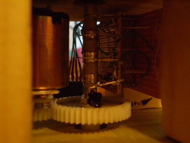
The bottom slip-ring assembly and gear reduction.

Assembled.
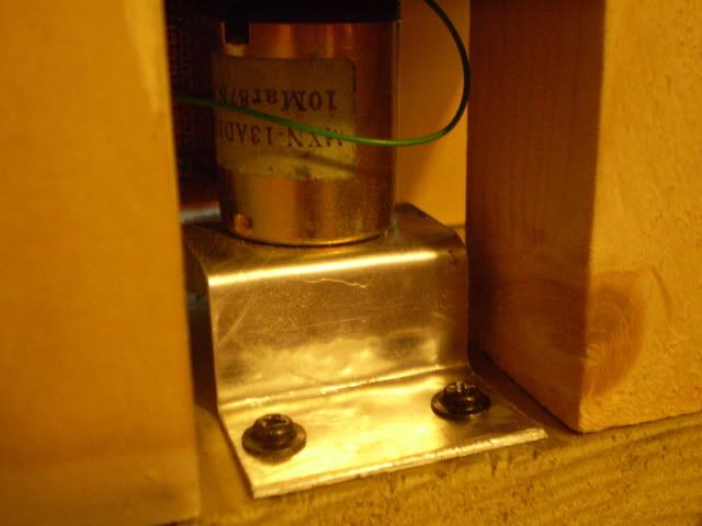
Home-made motor mount.
This big resistor limits the current to the first motor.

Modular connections.

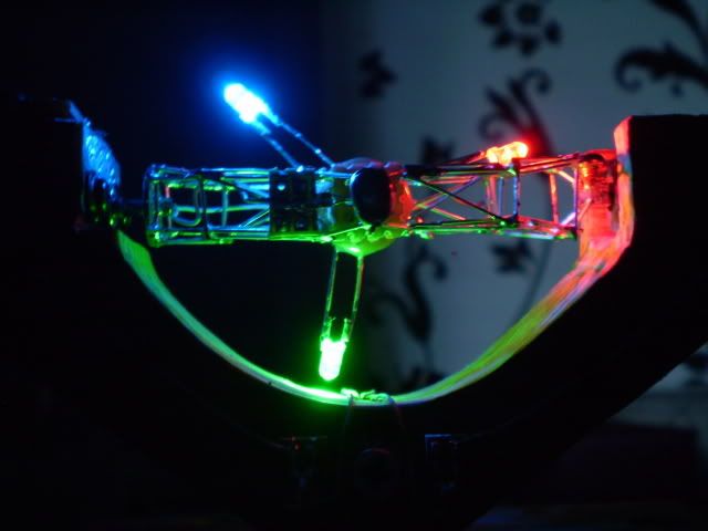
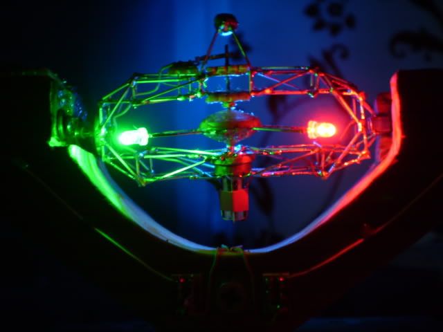
A few pictures in the dark. My camera does a very poor job at this
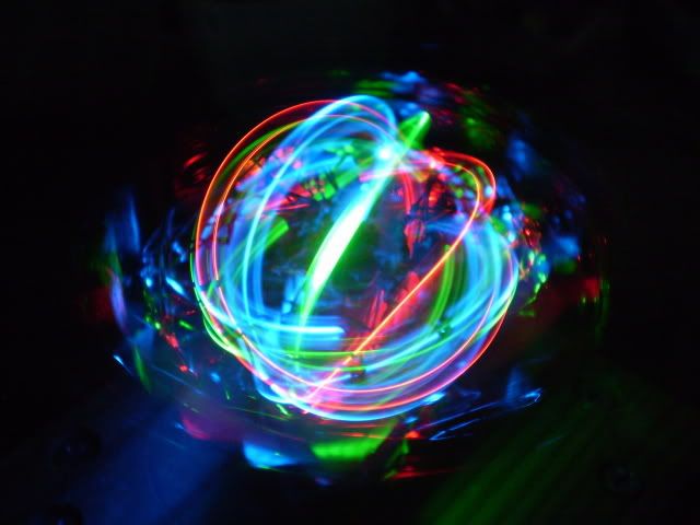
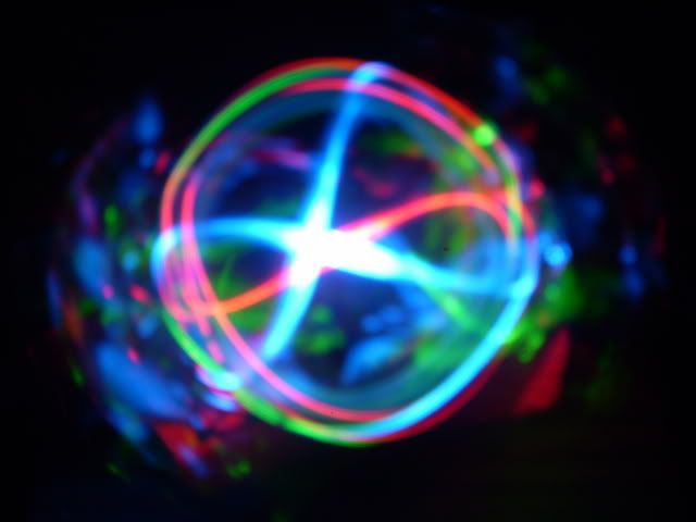
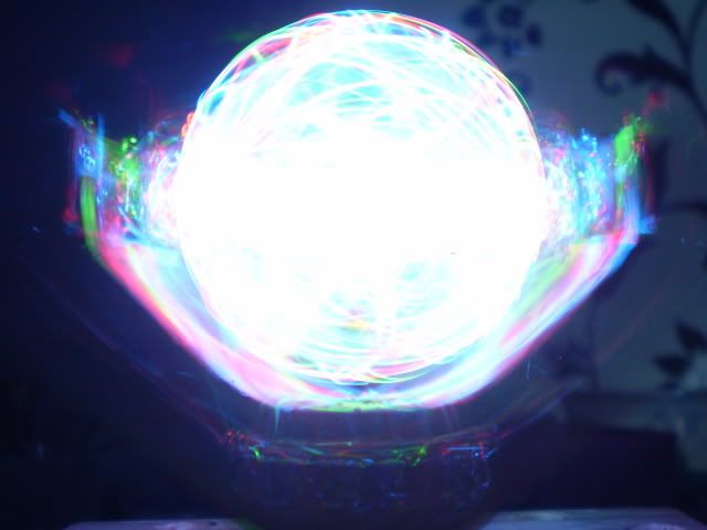
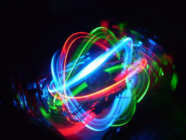
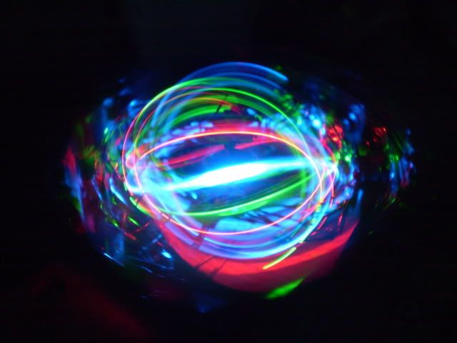
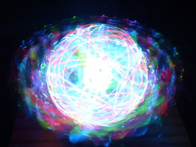
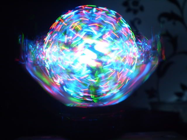
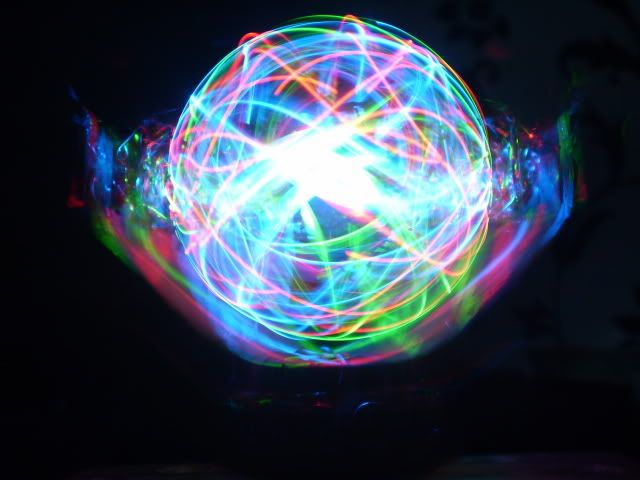
YouTube - Spinning RGB LED Ball II
It was very hard to build! I has a lot of problems with the power transfer and failed may times before I got everything working smoothly. Now it runs like a dream.
I made it all from very simple materials like wood, VCR-parts, fans, junk, antenna tubes and a lot of solder!
Total of 9 slip-contacts, not including the motors!
The current for the LEDs has travel through 6 slip-contact without glitching!
It took about a week to build.
(many) Pictures:
The device:

The controller. The unit to the left is a modified bike light, apparently if one of the resistors changed it's value, the frequency would also change. I replaced it with a 500K ohm pot and amplified the output with a transistor. The circuit has four modes: on - fast blink - slow blink - off.
The unit to the right is the motor controller. It's made of three 555-timer circuits that change the speed of the motors with pulse width modulation. It's the same controller I use for my spirographs and such.

A close-up of the head/nougat-core/whatever. Just three LEDs, one red, green and blue. The small DC-motor is a from a RC-heli that I got from my dad's colleague, thanks! The frame is made of a ton of leads from LEDs, they work best for this kind of thing because they are very stiff. Can I haz mad soldering skillz?!

The arrow points at a tiny spring who carries the positive voltage to the LEDs.

On the opposite side is the contact for the negative voltage. The big blob of solder is the counter weight.

The LEDs and their current limiting resistors are attached on a small perfboard, all in-closed in epoxy.


The second motor.

On the opposite side is the slip-ring assembly for the first motor and LEDs.

Pencil lead give the best results as a wiper contact!

Slip-rings made from antenna tubes.

The common connection.

Here are the four power wires from the base.

Here are the wiper contacts for the bottom axis. Made from LED-leads and perfboard.


The bottom slip-ring assembly and gear reduction.

Assembled.

Home-made motor mount.

This big resistor limits the current to the first motor.

Modular connections.

A few pictures in the dark. My camera does a very poor job at this


Last edited by a moderator:


