- Joined
- Jan 12, 2008
- Messages
- 3,290
- Points
- 83
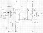
Here is how my driver looks, works very well:

Dots:
Red = bc337 NPN transistor
Orange = LM317 voltage regulator (DDL style)
Yellow = CNY17-3 opto isolator
Green = RGB LED IC, common anode (+).
Blue = 1N4001 to 1N4007 diode
Violet = 1 kohm resistor
Pink = 470 ohm resistor
Brown = laser diode
Gray = +12V
Squares:
Orange = lasing threshold resistor (around 50 ohm, 2W for green, 560 ohm 1/4W for red/violet). Some experimenting needed.
Green = max current resistor for laser diode (use ohm's law to find your value)
Blue = 100 ohm pot
Violet = 47µF 16V electrolytic capacitor
Pink = 100nF ceramic capacitor Not needed on the "BigClive-kit" as it comes with its own filter. The laser diode will need however.
Brown = 10 kohm pot (sensitivity adjust)
Gray = ground (negative)
The "BigClive-kit" runs off of 12V, if you use it you wont need the 470 ohm resistor in series with it.
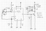
I also had a similar idea as Localghost, but I never tried it:

I'd like to know what's the smallest output capacitor could be, without risking the diode?
Good luck to your experiments and keep posting!")
Dots:
Red = bc337 NPN transistor
Orange = LM317 voltage regulator (DDL style)
Yellow = CNY17-3 opto isolator
Green = RGB LED IC, common anode (+).
Blue = 1N4001 to 1N4007 diode
Violet = 1 kohm resistor
Pink = 470 ohm resistor
Brown = laser diode
Gray = +12V
Squares:
Orange = lasing threshold resistor (around 50 ohm, 2W for green, 560 ohm 1/4W for red/violet). Some experimenting needed.
Green = max current resistor for laser diode (use ohm's law to find your value)
Blue = 100 ohm pot
Violet = 47µF 16V electrolytic capacitor
Pink = 100nF ceramic capacitor Not needed on the "BigClive-kit" as it comes with its own filter. The laser diode will need however.
Brown = 10 kohm pot (sensitivity adjust)
Gray = ground (negative)
The "BigClive-kit" runs off of 12V, if you use it you wont need the 470 ohm resistor in series with it.
I also had a similar idea as Localghost, but I never tried it:
I'd like to know what's the smallest output capacitor could be, without risking the diode?
Good luck to your experiments and keep posting!
Last edited: