LPF Donation via Stripe | LPF Donation - Other Methods
Links below open in new window
ArcticMyst Security by Avery


You are using an out of date browser. It may not display this or other websites correctly.
You should upgrade or use an alternative browser.
You should upgrade or use an alternative browser.
FusionDrives GB - CLOSED
- Thread starter BlueFusion
- Start date


pwnstar
0
- Joined
- Sep 12, 2007
- Messages
- 712
- Points
- 0
busterhax said:to bluefusion: SenKat is not assembling anymore drivers, i paid you for an assembled driver. any way i can get some type of compensation?
compensation of what? 2$???
anyways, mine arrived today.
Thanks so much senkat.
")
Edit:
Instructions for people too lazy to do a simple search for them
http://hacylon.case.edu/laser/Fusion_Drive_assembly_instructions.pdf
Edit:
(after seeing those nice pics I feel mean! lol nice job)
- Joined
- Dec 26, 2007
- Messages
- 682
- Points
- 28
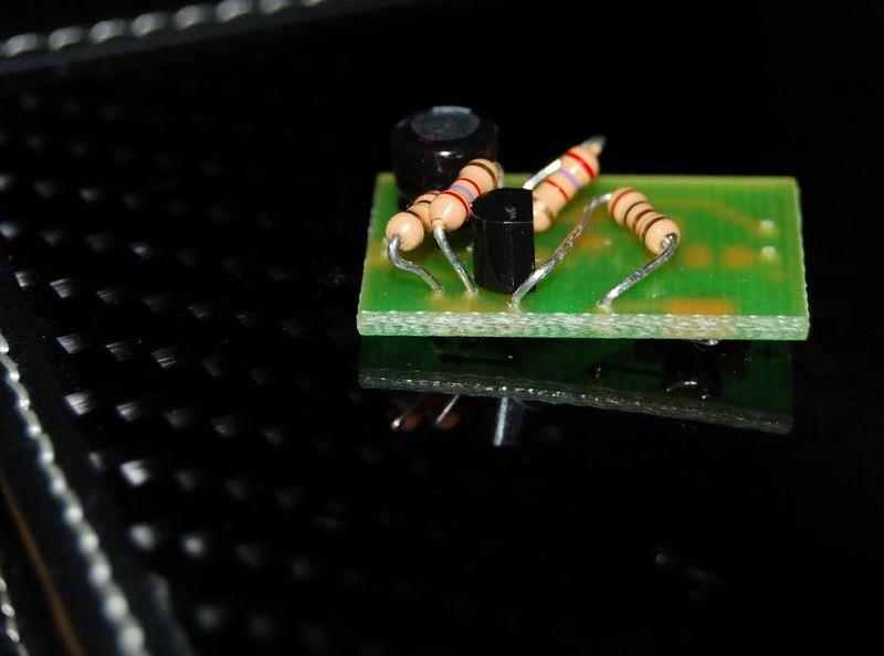
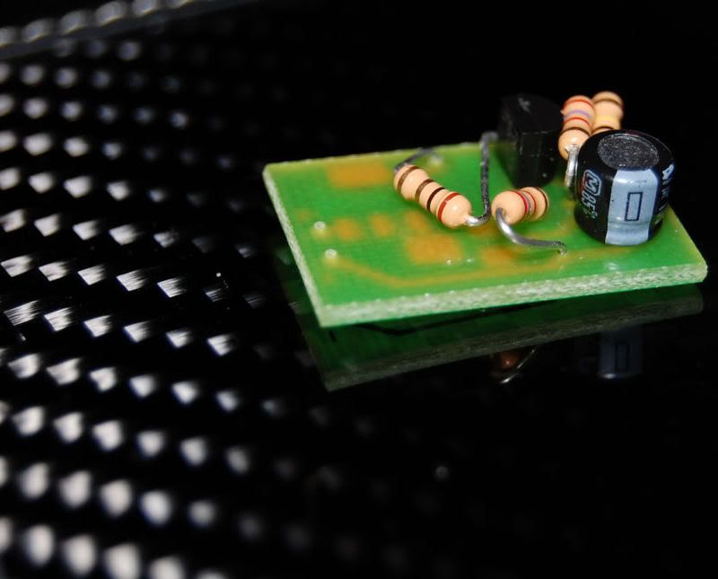
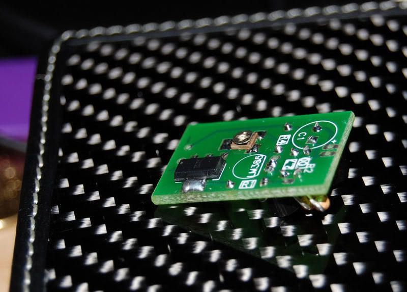
Received mine today, Thanks Greg! ;D
Kenom
0
- Joined
- May 4, 2007
- Messages
- 5,629
- Points
- 63
Kenom
0
- Joined
- May 4, 2007
- Messages
- 5,629
- Points
- 63
- Joined
- Dec 26, 2007
- Messages
- 682
- Points
- 28
Does anyone know what the "ohm-range" is for the little "pots" in these kits?
DH
DH
Kenom
0
- Joined
- May 4, 2007
- Messages
- 5,629
- Points
- 63
1K OHM pot.
I got my drivers Thank You so much SenKat
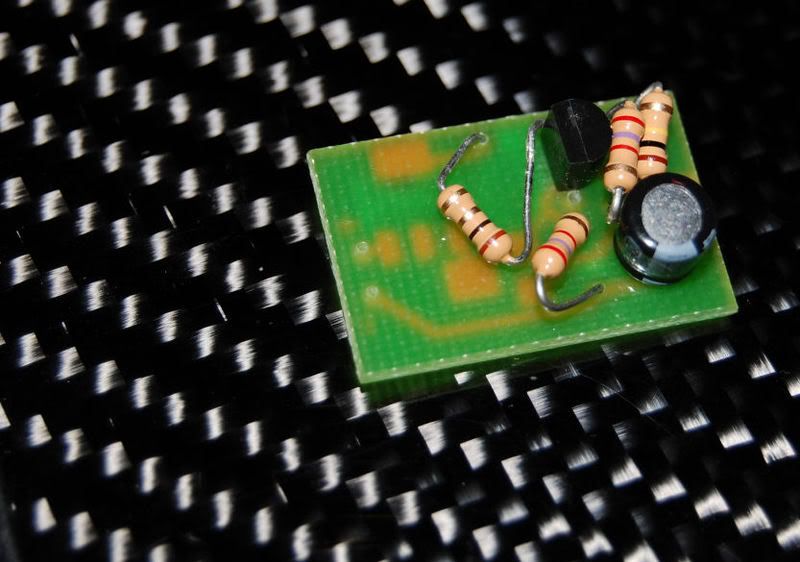
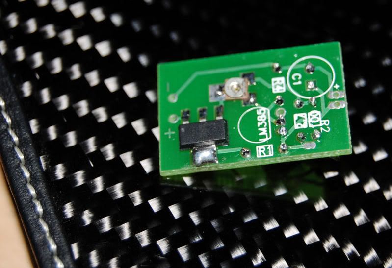
I was checking the board and found 2 holes that stand alone and don't connect to anything.
Its the same on all three boards the other two are still in an uncut form, I've illustrated in a picture
(Yes I cut the board down to fit in a Minimag tube, I'm from CPF)
I have a picture in my photobucket and will post it after I rack up 10 posts
The board is very different from the original blueprint so I can't figure where resistors 100k and 2.7k need to be connected.
I think I should bridge them both to the figure-8 shaped pad coming from R1
Again there is infinite resistance between these pads and any other point on all three of my boards
Any advise would be greatly appreciated.
Kenom
0
- Joined
- May 4, 2007
- Messages
- 5,629
- Points
- 63
What is your username on CPF?
Its the same nein166Kenom said:What is your username on CPF?

Kenom
0
- Joined
- May 4, 2007
- Messages
- 5,629
- Points
- 63
Well, you can post the link to photobucket and I'll fix the link for ya. Just put a space inbetween www photobucket com and i'll post the fix. I've put that instruction manual together so will be able to help ya out. you can also look at the picture I posted a few posts back and see how I've put them together. they are pretty detailed pictures.
Kenom
0
- Joined
- May 4, 2007
- Messages
- 5,629
- Points
- 63
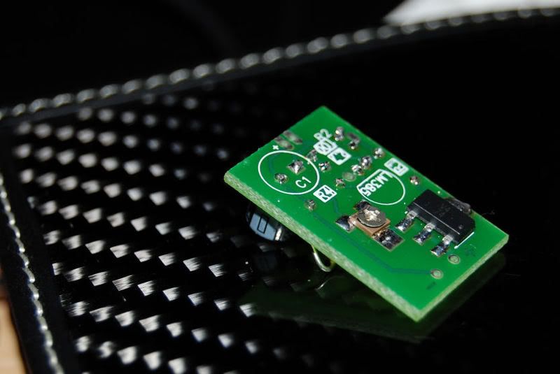
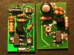
Ok now that you can post that picture. Your driver won't work. You cut one of the traces needed to go from the neg to r4. I don't see any way to salvage that other than making your own wire trace on the bottom side. However the two indicated resistors are in the correct place. Actually it can even be swapped around as you will select one or the other but only 1 for high or low range.
Right I should have posted the backside as well the neg path goes to R4 on the back and then on to C1 and then to diode ground pad.
So I think I understand that if I connect the 100K resistor to the pad as illustrated by the blue line for Bluray range 12-75ma I should be alright
So I think I understand that if I connect the 100K resistor to the pad as illustrated by the blue line for Bluray range 12-75ma I should be alright
