

danefex
0
- Joined
- Aug 30, 2010
- Messages
- 1,595
- Points
- 63
Greetings folks!
I'd like to share some pictures from another Lighthound AA build I finished today. I'm really happy with how this turned out & here's how it all came together.
I had an extra one of these Lighthound hosts from when I planned & built a powerful little (1W) purple 405 laser recently, also because I usually order 2 of everything hehe. Well since building and using the 405 a couple weeks ago, I've grown very attached to how it looks & feels when lasing! I didn't want to use it too much & shorten its precious lifespan, so I decided to use the other host to satisfy the craving and to make a monstrous little 445.:eg: I also wanted to try building a driver instead of using one like I always have, so I ordered some mohgasm parts & gave it all a shot. I documented the process of first assembling the driver & then building the laser, here's what it looked like.
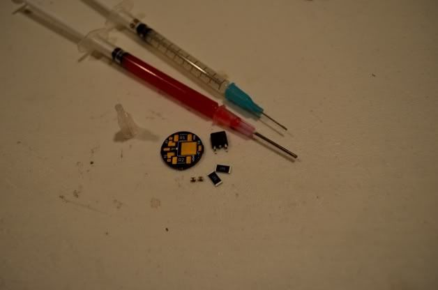
The Driver - Parts for a round linear Mohgasm 1.5A This is my first driver
build. I'm going to use 2 different types of flux, the red flux is thick &
helpful for bonding before soldering & the clear is thin for very small parts
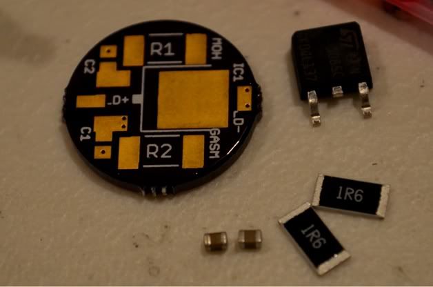
Close up of the parts
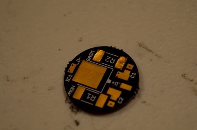
I'm going to start with the resistors. First I applied some thin flux on the
resistor contacts
Setting the resistor down on the flux, I held it in place with some tweezers
& soldered
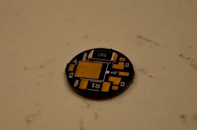
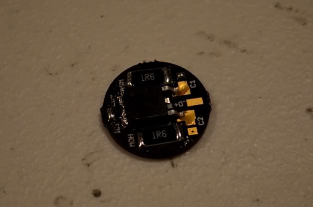
One resistor done
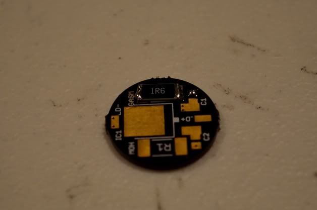
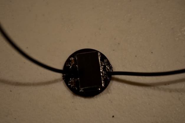
Both resistors soldered, now the regulator
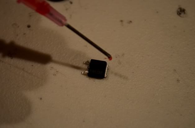
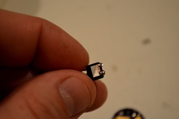
I'm going to flux & tin the regulator because it seems like it needs to be
pretty straight on the pcb
I dont know if tinning the contact & pressing it in place with a heatsink
clamp was the easier way to do this or not, but after heating the edges of
the contact I figured I could clamp it flat when the solder liquified
Here's the heatsink clamp I used to hold the regulator in place
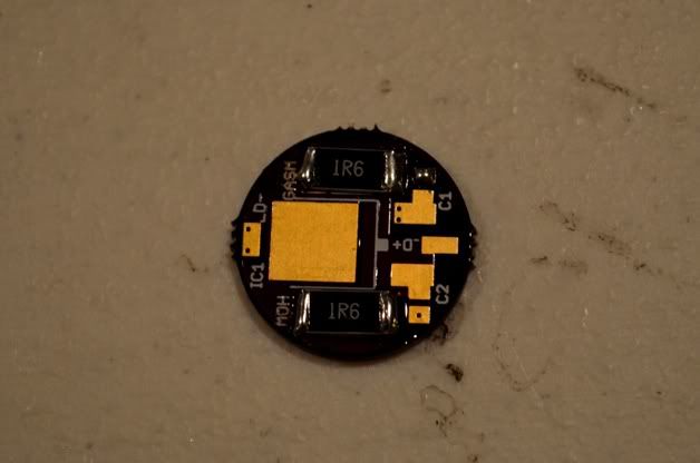
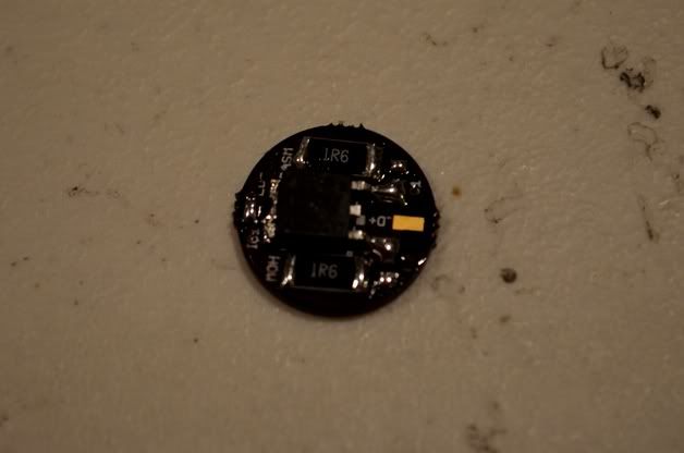
A success. Now fluxing the other ends
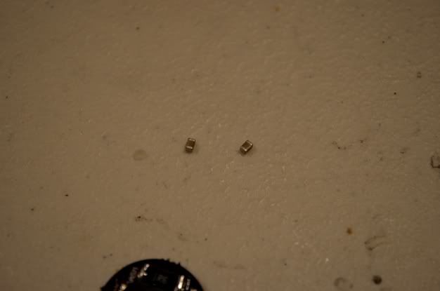
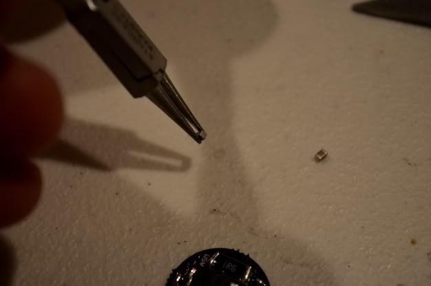
Easily soldered. Now to the smallest & the hardest part
Ugh, I made the mistake of dropping one of these little suckers on the floor.
About 25 minutes later, we can move on now :scowl:
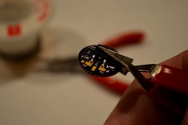
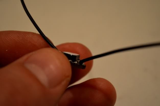
Basically what I did was flux and tin the contact points, then I used these
mini needle nose pliers to hold the caps
I cleared off all the solder from my iron & pressed the caps into place on the
tinned contact points
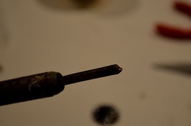
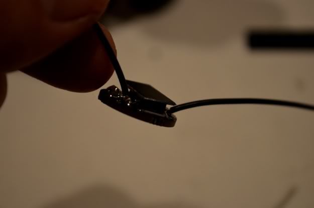
They both ended up soldering down on their edge, but the contact is good
& there's no shorts with the resistors
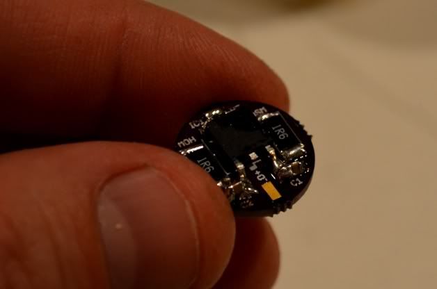
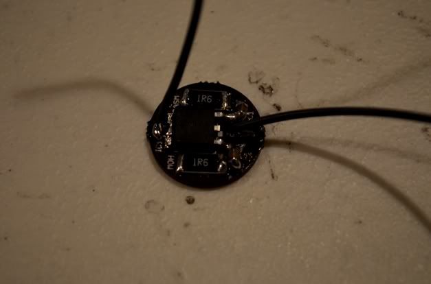
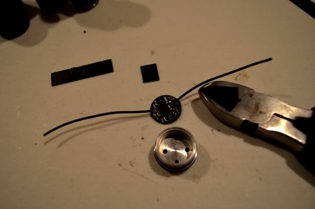
Added the wiring & the driver is done. I tested this driver & it worked, it
read at 1.5A on my DMM
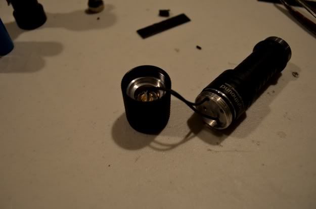
The Host - Lighthound 2xAA Tactical Flashlight
Parts - M140 445nm diode, Mohgasm 1.5A Driver, 405-G-1 lens, Jayrob
custom aluminum heatsink, 2x 14500 trustfire battieries

First thing I did here was heatsink the driver. I'm using black aluminum
strips I extracted from a pc graphics card heatsink to do this, cutting tabs
from these has proven very effective before
I used a thin layer of Arctic Silver for bonding the sink to the regulator
Pressed on the heatsink & let it dry for about 20 minutes
I made sure that none of the edges of the heatsink would extend past the
diameter of the driver
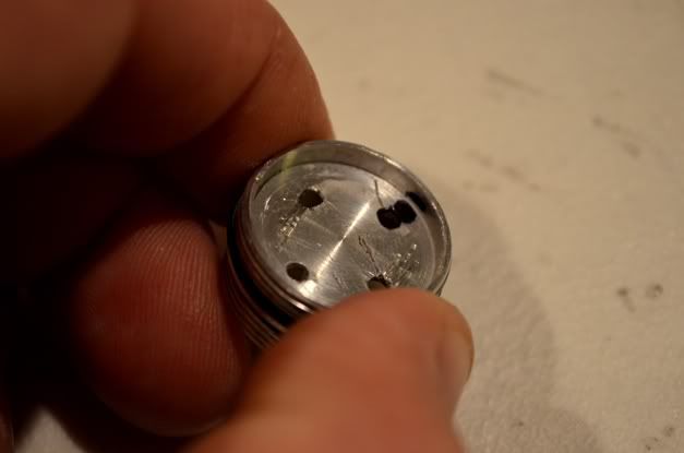
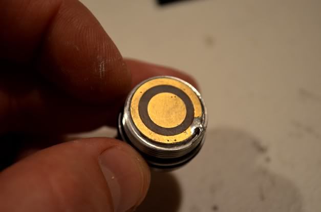
Next I marked the hole in the pill for polarity because I use the same color
wiring for these projects (also to confuse other people hehe)
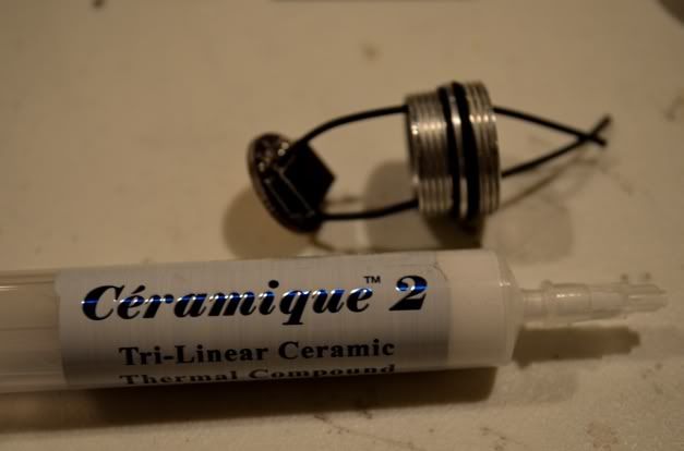
Before I mount & seal the driver in the pill, I'm going to use Ceramique 2
on the drivers' resistors AND to create a bond between the heatsink & the
pill. Why Ceramique 2 instead of Arctic Silver?? Because Ceramique doesn't
bond or completely dry, if I ever have problems with this build I can always
take it apart after cleaning up the mess
I aimed to fill it in good under there without making a mess
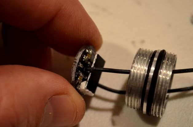
The first side was a little cleaner
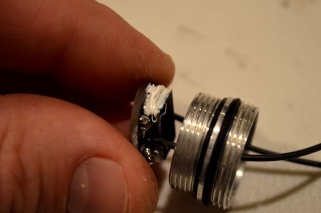
Next I added a big gob of Ceramique to the point in the pill where the
drivers heatsink will almost press against
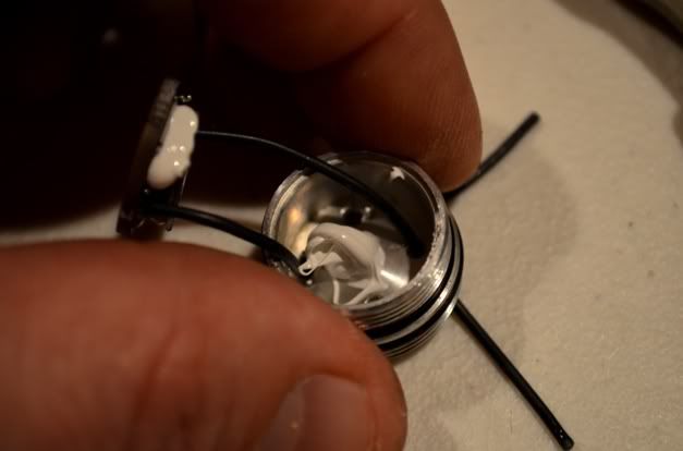
After pressing it all together, I noticed I had sanded down too much on the
edges of the battery contact. The contact wasn't secure in the pill, so I used
some Arctic Silver to hold it in place, then soldered a wedge between the
edge of the driver & the threading on the inside of the pill. The driver is now
secure in the pill & you can see the gap where the driver isn't touching
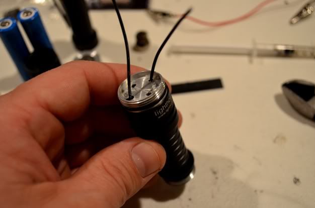
Screwed the pill into the top half of the host
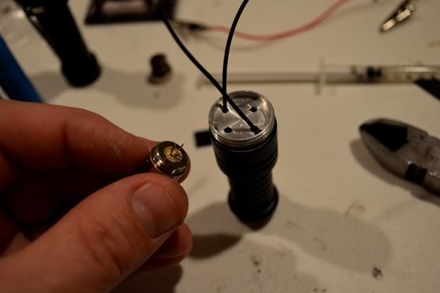
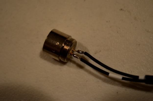
Grabbed the pre-pressed M140 for soldering
Added shrinktubing for protection
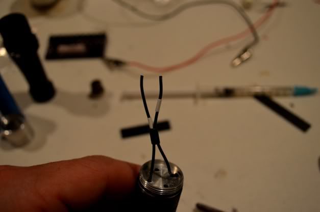
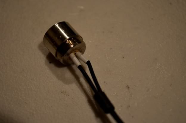
Soldered both leads
Covered the exposed areas
Turns out I didn't need the extra tubing, using that much length would mean
bending the diode pins on the face of the pill
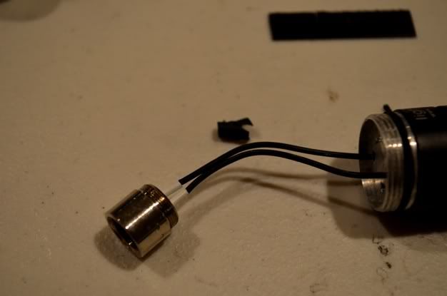
Installed the diode & module into the heatsink, then into the bezel
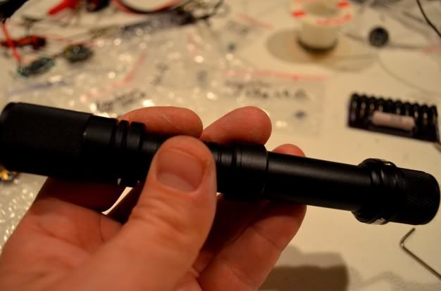
Added the top half of the host
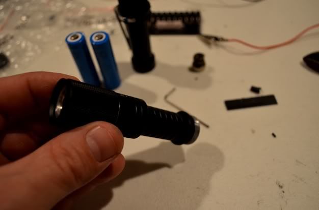
Screwed on the bottom half, installed the focus lens and its done!
Now to see where it hits on the LPM
Because of how small this laser is with this output power, there's no doubt the entire thing gets warm after about 1 min of runtime. That's good heatsinking though, thanks for checking this out & let me know what you think!! :beer:
I'd like to share some pictures from another Lighthound AA build I finished today. I'm really happy with how this turned out & here's how it all came together.
I had an extra one of these Lighthound hosts from when I planned & built a powerful little (1W) purple 405 laser recently, also because I usually order 2 of everything hehe. Well since building and using the 405 a couple weeks ago, I've grown very attached to how it looks & feels when lasing! I didn't want to use it too much & shorten its precious lifespan, so I decided to use the other host to satisfy the craving and to make a monstrous little 445.:eg: I also wanted to try building a driver instead of using one like I always have, so I ordered some mohgasm parts & gave it all a shot. I documented the process of first assembling the driver & then building the laser, here's what it looked like.
The Driver - Parts for a round linear Mohgasm 1.5A This is my first driver
build. I'm going to use 2 different types of flux, the red flux is thick &
helpful for bonding before soldering & the clear is thin for very small parts
Close up of the parts
I'm going to start with the resistors. First I applied some thin flux on the
resistor contacts
Setting the resistor down on the flux, I held it in place with some tweezers
& soldered
One resistor done
Both resistors soldered, now the regulator
I'm going to flux & tin the regulator because it seems like it needs to be
pretty straight on the pcb
I dont know if tinning the contact & pressing it in place with a heatsink
clamp was the easier way to do this or not, but after heating the edges of
the contact I figured I could clamp it flat when the solder liquified
Here's the heatsink clamp I used to hold the regulator in place
A success. Now fluxing the other ends
Easily soldered. Now to the smallest & the hardest part
Ugh, I made the mistake of dropping one of these little suckers on the floor.
About 25 minutes later, we can move on now :scowl:
Basically what I did was flux and tin the contact points, then I used these
mini needle nose pliers to hold the caps
I cleared off all the solder from my iron & pressed the caps into place on the
tinned contact points
They both ended up soldering down on their edge, but the contact is good
& there's no shorts with the resistors
Added the wiring & the driver is done. I tested this driver & it worked, it
read at 1.5A on my DMM
The Host - Lighthound 2xAA Tactical Flashlight
Parts - M140 445nm diode, Mohgasm 1.5A Driver, 405-G-1 lens, Jayrob
custom aluminum heatsink, 2x 14500 trustfire battieries
First thing I did here was heatsink the driver. I'm using black aluminum
strips I extracted from a pc graphics card heatsink to do this, cutting tabs
from these has proven very effective before
I used a thin layer of Arctic Silver for bonding the sink to the regulator
Pressed on the heatsink & let it dry for about 20 minutes
I made sure that none of the edges of the heatsink would extend past the
diameter of the driver
Next I marked the hole in the pill for polarity because I use the same color
wiring for these projects (also to confuse other people hehe)
Before I mount & seal the driver in the pill, I'm going to use Ceramique 2
on the drivers' resistors AND to create a bond between the heatsink & the
pill. Why Ceramique 2 instead of Arctic Silver?? Because Ceramique doesn't
bond or completely dry, if I ever have problems with this build I can always
take it apart after cleaning up the mess
I aimed to fill it in good under there without making a mess
The first side was a little cleaner
Next I added a big gob of Ceramique to the point in the pill where the
drivers heatsink will almost press against
After pressing it all together, I noticed I had sanded down too much on the
edges of the battery contact. The contact wasn't secure in the pill, so I used
some Arctic Silver to hold it in place, then soldered a wedge between the
edge of the driver & the threading on the inside of the pill. The driver is now
secure in the pill & you can see the gap where the driver isn't touching
Screwed the pill into the top half of the host
Grabbed the pre-pressed M140 for soldering
Added shrinktubing for protection
Soldered both leads
Covered the exposed areas
Turns out I didn't need the extra tubing, using that much length would mean
bending the diode pins on the face of the pill
Installed the diode & module into the heatsink, then into the bezel
Added the top half of the host
Screwed on the bottom half, installed the focus lens and its done!
Now to see where it hits on the LPM
Because of how small this laser is with this output power, there's no doubt the entire thing gets warm after about 1 min of runtime. That's good heatsinking though, thanks for checking this out & let me know what you think!! :beer:
Last edited:


