Welcome to Laser Pointer Forums - discuss green laser pointers, blue laser pointers, and all types of lasers

LPF Donation via Stripe | LPF Donation - Other Methods

Links below open in new window

ArcticMyst Security by Avery

what to solder?

lman

0
Joined
Feb 23, 2012
Messages
298
Points
0
ignor the vid just put the postive connection through the driver or just the neg connection


Joined
Mar 9, 2012
Messages
55
Points
0
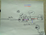
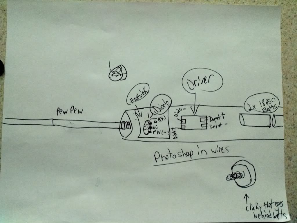
Perhaps it would be helpful if you drew a schematic of how you are connecting things. It depends on the driver wether you need to have the diode connected to the case, and how to wire the driver exactly.

Also, you generally cannot solder anything onto aluminium with equipment used to solder electronics.

IMG_20120325_214335.jpg


Would be great if you could explain where the wires go or Photoshop them in. The diode is a lpc-826 running on 355ma frôm the driver
 
Joined
Mar 9, 2012
Messages
55
Points
0
To tell you the truth, all i'm asking is if the negative current needs to beregulated. I got the solder thing down
 

lman

0
Joined
Feb 23, 2012
Messages
298
Points
0
Anyway good luck with your build you might want to try laser bug from modwrex.
 

Fiddy

0
Joined
May 22, 2011
Messages
2,726
Points
63
blind leading the blind lol

the driver will be a positive regulator.

What driver are you using?
 

Fiddy

0
Joined
May 22, 2011
Messages
2,726
Points
63
attached is completed connection diagram.
 

Attachments

  • connection.png
    connection.png
    597.3 KB · Views: 530
Joined
Oct 26, 2007
Messages
5,438
Points
83
Is that diagram correct? The driver negative output is connected to the diode's case non-connect pin.


Top