jayrob
0
- Joined
- Sep 21, 2007
- Messages
- 9,862
- Points
- 113
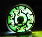
lamborgini8 said:If you look at the little round board, is the outer contact part needed where it meets the spring?
A guy here helped wire up my build and he insisted it was not needed and would just be shorting it so he took the liberty of cutting the track. The build just refuses to work now, it is definatly wired up correctly so I am lost if thats not what the problem is...
I'm sure you could make it work with out the metal ring that I show 'cut down' in the pictures. (first post)
But the method I used to get ground, is to use this metal ring to push up against the circuit board. So that the host (negative) pushes up against the ring, and the ring touches the outer contact points on the round circuit board. Which I used for the negative lead to the FlexDrive.
This is the only way I have done the build, but there are other ways. You just have to have good contact from the host to the negative side of the FlexDrive, and good contact from the center contact on the circuit to the positive side of the FlexDrive input.
Then the output leads to the diode...
Jay


")