

KiLLrB
0
- Joined
- Jan 27, 2010
- Messages
- 1,072
- Points
- 48
Ok I have searched the internet for a tutorial on disassembling a Melles Griot head to remove the plasma tube. I found a couple that were very vague and had no pictures so I decided to give it a try myself and document it with pictures as i went...
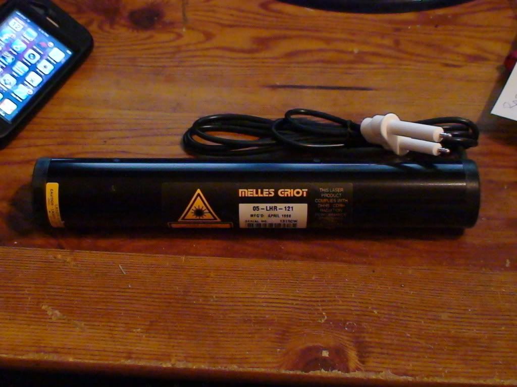
Ok so the specimen in question is a 05-LHR-121 laser head as seen below:
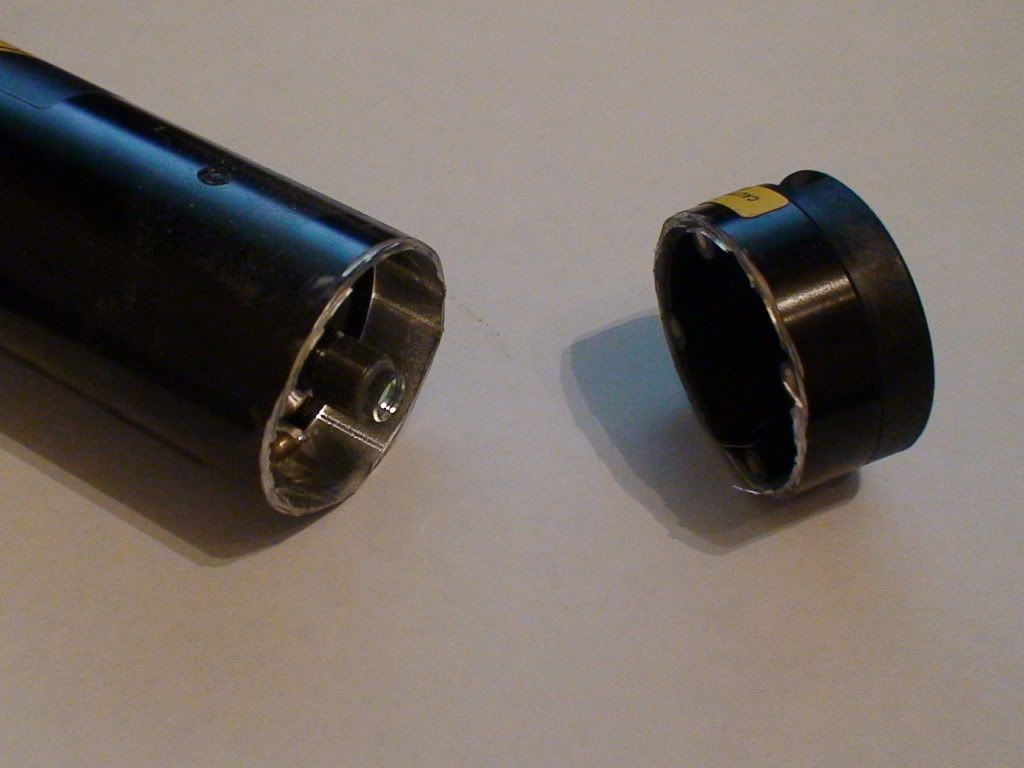
So the first thing I decided to do was to remove the end caps starting with the shutter at the aperature end cutting about 1cm back from where the plastic meets the aluminum being VERY careful not to cut too deep into the housing with my dremel. Please be sure to wear the proper protective eyewear. :
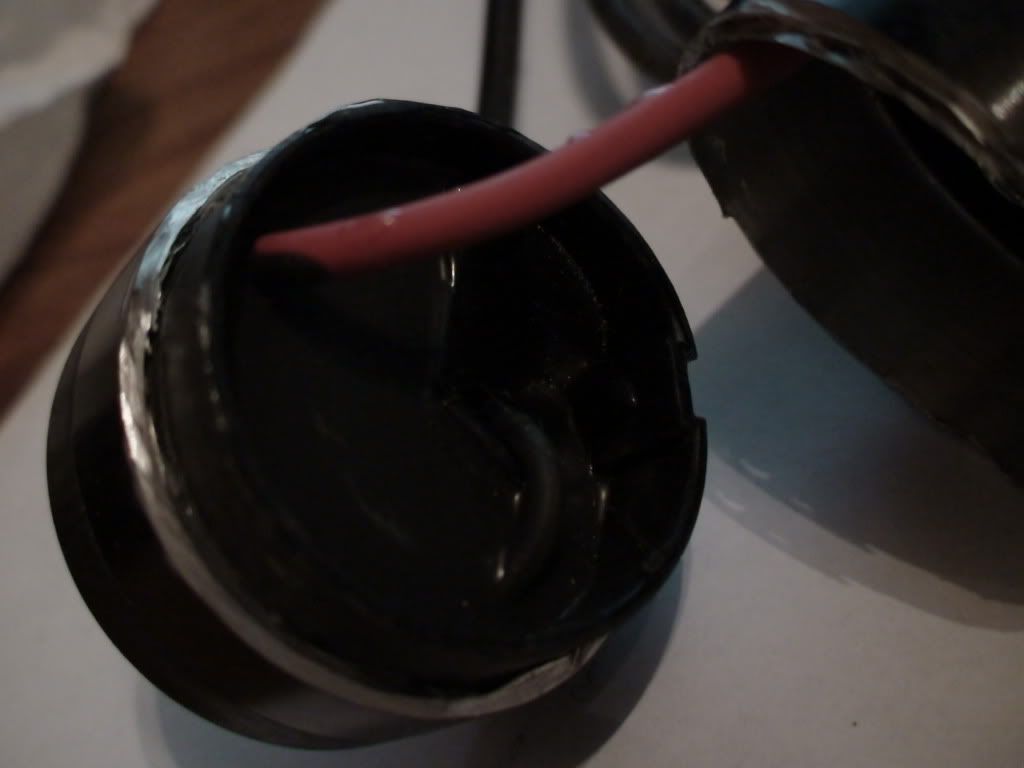
Then we move to the back end of the housing where the power for the tube enters the housing. I also chose to cut about 1cm back from where the plastic meets the aluminum and this worked nicely as it was far enough back to get past the epoxy but not so far as to get past the plastic cap so the cap could serve as a guard to keep from cutting too deep:
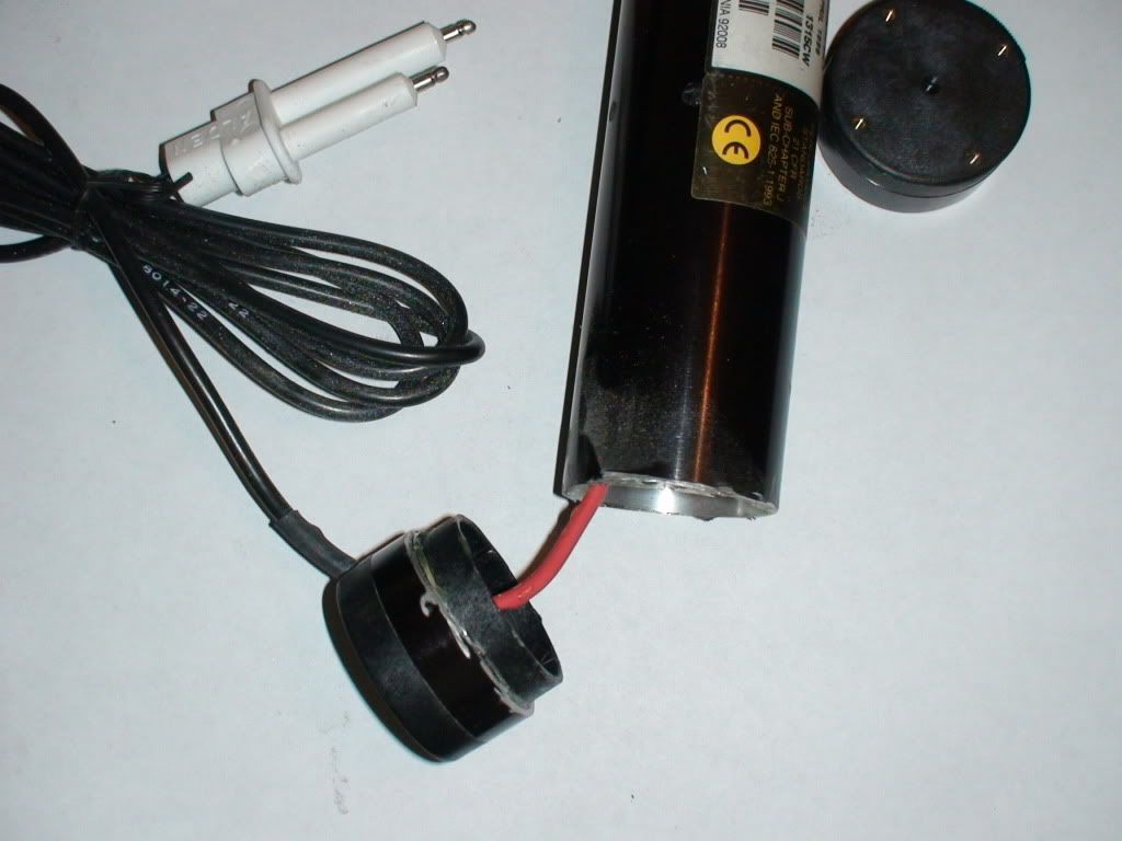
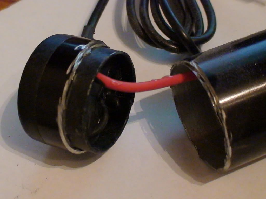
Now with the tailcap removed I noticed there is only one lead going to the laser this is because the housing serves as the cathode lead to make the connection to the front of the tube. I now cut the anode wire close to the tailcap to leave enough wire to allow for an easy connection later. Now as you can see below there is a potting material in the tailcap. This potting material contains the ballast resistor and the cathode connection to the housing. The material is most likely and RTV silicone and is somewhat easy to break up and crumble to get to the ballast resistor which will need to be removed to be resoldered into the circuit later.
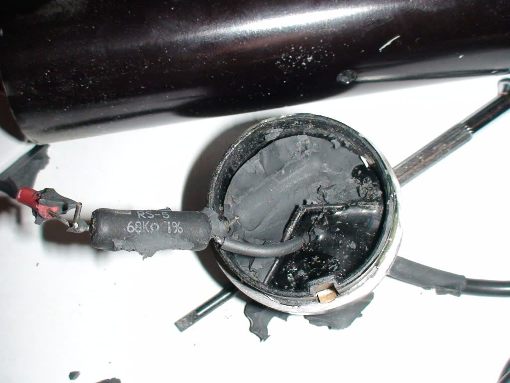
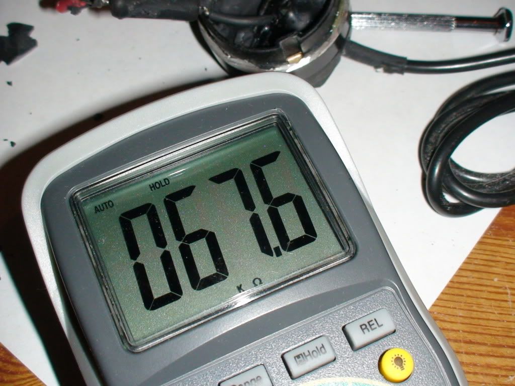
You'll notice the Ballast resistor calls for 68Kohms out of curiosity i tested it to be sure it was in spec and everything seemed to be in order:
Now to the fun part... Removing the tube!
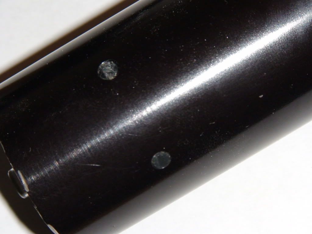
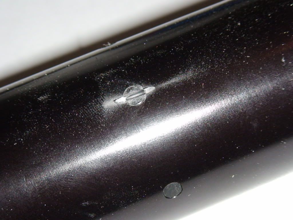
If you'll look closely on the sides you will see two rows of little black spots circumnavigating the tube. Every other one in each row is alternating one being a nylon set screw (hard and broke off) to position the tube in the housing and the other is a hotglue (obviously the softer material) which is used as the potting material.
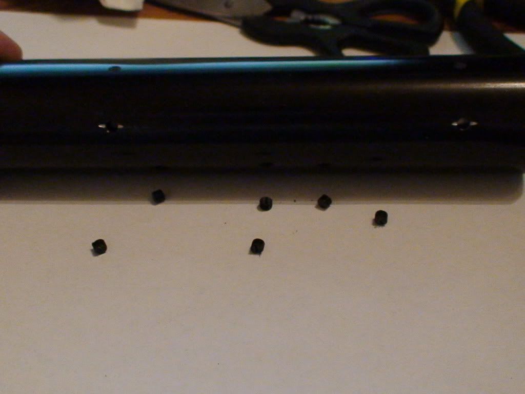
First you will need to remove the nylon set screws. I accomplished this by cutting slots in the screws and removing them with a flat screwdriver afterwards:
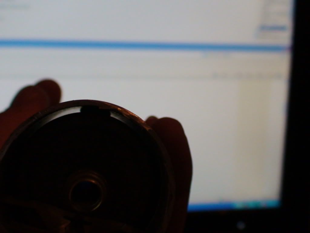
Now to take care of the hotglue potting... If you look in the picture below you will see and end on view of the tube with the potting in view and luckily it is minimal.
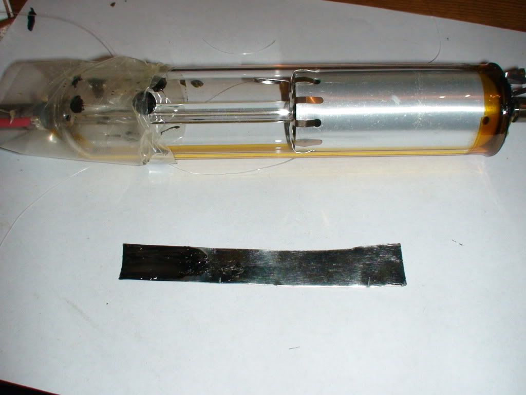
Now there have been a few suggestions on Sam's FAQ about how to take care of this problem such as guitar/piano string and others. I chose to use a piece of aluminum flashing. I cut it into a narrow strip and heated it with a lighter to break the connection of the glue to the housing which worked relatively easy. I tried very carefully to keep the strip close to the housing as not to scratch the tube. After cutting all of the seals I used a piece of plastic to push the tube out of the housing being especially careful not to bump the mirrors. Once the tube is out the hotglue peels off really easy.
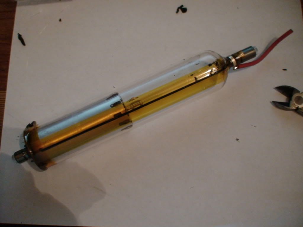
...and after a little cleaning
TADA! now to see if it works
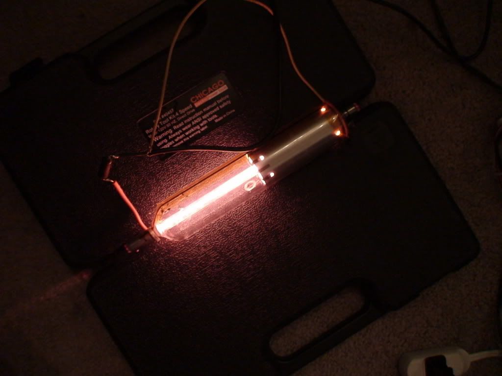
Sucess!!!!
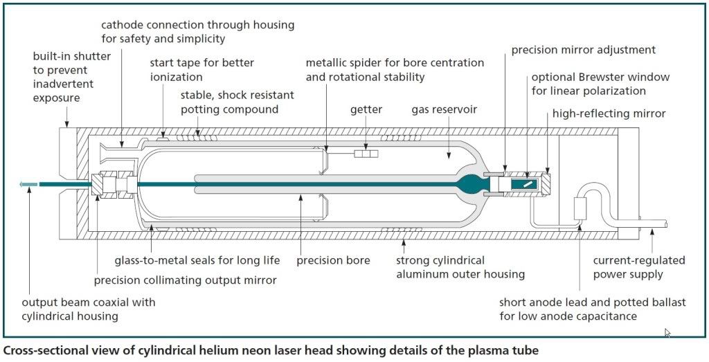
Here is a cross section from Melles Griot's website that may prove useful:
Ok so the specimen in question is a 05-LHR-121 laser head as seen below:
So the first thing I decided to do was to remove the end caps starting with the shutter at the aperature end cutting about 1cm back from where the plastic meets the aluminum being VERY careful not to cut too deep into the housing with my dremel. Please be sure to wear the proper protective eyewear. :
Then we move to the back end of the housing where the power for the tube enters the housing. I also chose to cut about 1cm back from where the plastic meets the aluminum and this worked nicely as it was far enough back to get past the epoxy but not so far as to get past the plastic cap so the cap could serve as a guard to keep from cutting too deep:
Now with the tailcap removed I noticed there is only one lead going to the laser this is because the housing serves as the cathode lead to make the connection to the front of the tube. I now cut the anode wire close to the tailcap to leave enough wire to allow for an easy connection later. Now as you can see below there is a potting material in the tailcap. This potting material contains the ballast resistor and the cathode connection to the housing. The material is most likely and RTV silicone and is somewhat easy to break up and crumble to get to the ballast resistor which will need to be removed to be resoldered into the circuit later.
You'll notice the Ballast resistor calls for 68Kohms out of curiosity i tested it to be sure it was in spec and everything seemed to be in order:
Now to the fun part... Removing the tube!
If you'll look closely on the sides you will see two rows of little black spots circumnavigating the tube. Every other one in each row is alternating one being a nylon set screw (hard and broke off) to position the tube in the housing and the other is a hotglue (obviously the softer material) which is used as the potting material.
First you will need to remove the nylon set screws. I accomplished this by cutting slots in the screws and removing them with a flat screwdriver afterwards:
Now to take care of the hotglue potting... If you look in the picture below you will see and end on view of the tube with the potting in view and luckily it is minimal.
Now there have been a few suggestions on Sam's FAQ about how to take care of this problem such as guitar/piano string and others. I chose to use a piece of aluminum flashing. I cut it into a narrow strip and heated it with a lighter to break the connection of the glue to the housing which worked relatively easy. I tried very carefully to keep the strip close to the housing as not to scratch the tube. After cutting all of the seals I used a piece of plastic to push the tube out of the housing being especially careful not to bump the mirrors. Once the tube is out the hotglue peels off really easy.
...and after a little cleaning
TADA! now to see if it works
Sucess!!!!
Here is a cross section from Melles Griot's website that may prove useful:
Last edited:

