Welcome to Laser Pointer Forums - discuss green laser pointers, blue laser pointers, and all types of lasers

LPF Donation via Stripe | LPF Donation - Other Methods

Links below open in new window

ArcticMyst Security by Avery

"Triple Silver Guidesman" - DIY 1650mA LM1117 Build

rhd

0
Joined
Dec 7, 2010
Messages
8,475
Points
0
This builds on some of the discussions from driver threads re: combining LM317 ICs to achieve higher currents.

Didn't have much luck with the LM317s on two li-ion cells, powering a 445. But I've found that combining THREE of the lower drop-out LM1117s, along with the balancing resistor design anselm found, worked quite well!

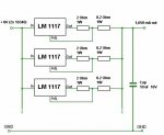
Here's the circuit I settled on:
attachment.php


The 2 Ohm resistors would suggest a total output of ~1800 mA. Ultimately the design resulted in a consistent 1650 mA. I'm chalking the shortfall up to the balancing resistors.

At ~600mA per Lm1117, we're running them under their suggested current limit. They don't seem to get particularly hot.

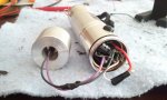
Here's a shot of the guts all stuffed in the guidesman host. I used a stiff piece of copper, wound in a single circle around the inside of the host (soldered to the walls) to retrieve the (-) from the case.
attachment.php


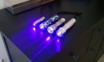
And here it is next to Pocket Mini Chrome, my "Guerrilla Blue" build (1,000mA), and my "Indie Bullet" which although 1,600mA at the time of writing that thread, has now been rewired with the same 1,000 mA driver as my Guerrilla Blue.
attachment.php


You can tell in the photo, but it's even more obvious in real life that this build is noticeably higher powered than the other three.

Hope someone enjoys this thread :)
 

Attachments

  • rhd2.jpg
    rhd2.jpg
    55.8 KB · Views: 11,823
  • guts.jpg
    guts.jpg
    121.8 KB · Views: 3,720
  • all.jpg
    all.jpg
    107.7 KB · Views: 3,698


Joined
Aug 7, 2010
Messages
2,086
Points
0
You... again??
Damn boy, you need to give a break between builds so people can rep you again :shhh:

"You must spread some Reputation around before giving it to rhd again."

:beer:


Edit:
ooooh btw, the 2 ohm resistors should not limit the current out as you built. The only thing limiting the output there should be the balancing 0.2 ohm resistors :beer:
 
Joined
Nov 10, 2008
Messages
4,186
Points
63
Impressive build man. Very nice work. +1 But answer me this question. Considering each lm1117 has a vdrop of ~2.2 V ( sorry i cant remember how much exactly ), wouldn't the whole driver have a total vdrop of 3x2.2 V ?
 
Joined
Aug 7, 2010
Messages
2,086
Points
0
@Silvershot
No. Because the drivers are paralleled, not series (even I don't think series drivers are possible lol) :D

dropout = 1.5v (2.5v for 317)
 
Joined
Nov 10, 2008
Messages
4,186
Points
63
Holy shi*t, I MUST build one driver like this :eek: that's insanely epic, to have same drop as though you were using only one regulator :) Thanks for clarifying that, Leodahsan :beer:

@rhd, is it a trouble getting some photos of the wiring you did on the components? I can see everything pushed in there but that's kind of,err tricky if something breaks isnt it? Also, thanks for the schematic :beer:

P.S Damn thats the old good lpf I knew. Lot's of DIY work everyday. Keep it up folks :)
 
Joined
Aug 7, 2010
Messages
2,086
Points
0
@Silvershot
hey, call me Leo ok? NP! :beer:
unfortunately he needs balancing resistors, that lower the output a bit. Still a great deal :beer:

Soon you will see what is a REAL DIY............ :D
 

rhd

0
Joined
Dec 7, 2010
Messages
8,475
Points
0
Silvershot: It's actually around 1.5V (+/- a bit), and they're in parallel, so the vdrop doesn't get multiplied.

And yes, very tricky if something breaks. If that happens, I'm building a new driver :) It's not actually chaos - there's quite a bit of "organization" inside that tiny driver pill - it just doesn't look like it from above!

Leo: Those balancing resistors were key to making it all work.

And I have one more crazy build up my sleeve tonight, then I'm hittin the books for a while :)
 

anselm

0
Joined
Nov 22, 2010
Messages
2,448
Points
0
Awesome how you put our combined "research" into practice!
Do you have a link to buy a dozen of these ICs?
 

rhd

0
Joined
Dec 7, 2010
Messages
8,475
Points
0
Hey Leo:
What's my mistake?

Anselm:
I got mine on eBay. Search "LM1117 adj"

The "adj" is important - you don't want a fixed voltage version.

They're dirt cheap from China - like $10 shipped for 50x.
 
Joined
Aug 7, 2010
Messages
2,086
Points
0
@rhd
the output goes thru the OUT, not thru the ADJ, hence you need to let the output pass only thru the 0.2ohm resistor, not by the 2 ohm AND by the 0.2 ohm. People say that the driver goes UNSTABLE but the results were inconclusive. I personally prefer doing it the right way than the bad way but thats just me :beer:
 
Joined
Nov 10, 2008
Messages
4,186
Points
63
@rhd
the output goes thru the OUT, not thru the ADJ, hence you need to let the output pass only thru the 0.2ohm resistor, not by the 2 ohm AND by the 0.2 ohm. People say that the driver goes UNSTABLE but the results were inconclusive. I personally prefer doing it the right way than the bad way but thats just me :beer:

If you take a look at the famous DDL driver, the is also a resistor or two connected in parallel to the ADJ and OUT pins of the lm317. Why would it be harmful by any means?
 

rhd

0
Joined
Dec 7, 2010
Messages
8,475
Points
0
@rhd
the output goes thru the OUT, not thru the ADJ, hence you need to let the output pass only thru the 0.2ohm resistor, not by the 2 ohm AND by the 0.2 ohm. People say that the driver goes UNSTABLE but the results were inconclusive. I personally prefer doing it the right way than the bad way but thats just me :beer:

No - it goes out through the ADJ. That graphic lays out the inputs confusingly, which is probably what is throwing you. Take a look at the typical DDL:

LM317%20components01.jpg


The output is going out of the "left-most" pin. Take a look at a pinout of the LM317 (same as LM1117)
LM317.jpg


That's the "ADJ" pin.

Remember, we're wiring these up differently since they're being used as current regulators, not voltage regulators. My wiring was correct. The diagram I plagiarized is also correct, but definitely confusing.

At least - that's my take. I could be wrong on some or all of the above :)
 
Joined
Aug 7, 2010
Messages
2,086
Points
0
I never noticed that the output gone thru the ADJUST pin. That does not sound OK for me but, as it worked for ALL people that builded that driver, I AM WRONG :beer:

Thanks for noticing me guys.


Top