Welcome to Laser Pointer Forums - discuss green laser pointers, blue laser pointers, and all types of lasers

LPF Donation via Stripe | LPF Donation - Other Methods

Links below open in new window

ArcticMyst Security by Avery

Question about power rating clickie.

Joined
Oct 26, 2007
Messages
5,438
Points
83
HAH!, my favorite part is when they have values for driving capacitive and inductive loads with DC. Good luck with that. :crackup:They have a fundamental misunderstanding of most of the AC load types, too.

Lamps aren't shorts. Go measure the resistance of a light bulb - it's not zero. Sure, the inrush current can be a few times steady-state, but it's for a measly few milliseconds.

Lamps act like shorts in the sense that they draw 20 or more times their normal operating current when first turned on. Yes, and those "measly few milliseconds" are quite relevant to the switch rating.

All DC loads are resistive. If you put an inductor on a DC source, either the source or the inductor blows up. If you put a capacitor on a DC source, either nothing happens, or the DC source blows from the inrush current if the cap is particularly large.

You're thinking in terms of steady-state DC circuits. You can definitely have inductive and capacitive loads in a DC circuit, and these are especially relevant when a switch is thrown, generating a step-function.

Remember that switch ratings are not concerned with the steady-state current, but with the "instantaneous" changes that occur during the transition from on to off or vice versa.


AUS

0
Joined
Apr 12, 2012
Messages
565
Points
28
Inductors and capacitors definitely have a role to play at DC. A few quick examples spring to mind quickly before I race off to work:

Capacitors:
RC delay circuits where a delay happens due to the charge / discharge of a resistor and capacitor to T=RC.

Inductors:
Back EMF from switching off an inductive load coil discharges DC in the reverse direction when switched off which is why you use reverse diodes across relay coils. They're used in DC/DC converters, used in voltage regulation and limiting inrush current into DC circuits (used to be more common years ago but still used). DC-DC converters, old car ignition coils when used with points (no its not AC with a regular frequency and sinusodal waveform its pulsed DC).
 
Joined
Sep 12, 2007
Messages
9,399
Points
113
You're trying to make the case that pulsed DC isn't AC? Does the current not alternate? Do not all components in the circuit behave as if they are in an AC circuit? A square wave is still a wave, and waves are generally known to alternate.

Mechanical switching isn't done before the filter caps of DC supplies - it's done on the AC side. Besides, both a 1pF cap and a 1F cap are "capacitive loads." There is no set number you can use for this.

The cap charging in an RC circuit happens at a very low current - negligible when it comes to switches.

Motors... you've got me there. :undecided:

I was looking around, and the national electric code seems to think the current rating provides for incandescent lamps. I really don't think anyone in their right mind would derate a switch 80% for a light. Your typical wall switch is 10A, which means your lighting load would be limited to 240W (chandeliers are now off-limits?).
 
Last edited:
Joined
Dec 29, 2009
Messages
3,136
Points
63
Here's where I step in and say "a-hah! I found a mistake in Cyparagon's post!" to which I'm sure I'll receive a reply that teaches me yet another aspect of electronics, but isn't pulsed DC still current going in only one direction?

And keep up the energetic conversation!
 

AUS

0
Joined
Apr 12, 2012
Messages
565
Points
28
isn't pulsed DC still current going in only one direction?!

Yes, AC current reverses direction every cycle, pulsed DC only flows in one direction. DC maintains an arc better because the AC arc is "quenched" every half cycle by the opposite flow.

In laymans terms, it takes time to build up the arc again in the opposite direction.
 
Joined
Sep 12, 2007
Messages
9,399
Points
113
Yes, AC current...

Heheh, alternating current current? :p

isn't pulsed DC still current going in only one direction?

One direction with respect to what point? To ground?... kind of. It's more like move left, stop, Move left, stop. Your speed is in one direction, but your acceleration is in both directions.

Pulsed DC is just an AC square wave with a DC offset. That is to say it has a DC component and an AC component. This means it still behaves as AC would.

DC maintains an arc better because the AC arc is "quenched" every half cycle by the opposite flow.

And a pulsed DC arc would be quenched every cycle by forcing the voltage to zero.
 
Last edited:

AUS

0
Joined
Apr 12, 2012
Messages
565
Points
28
Heheh, alternating current current? :p

Yes, I missed that one, should have been AC current

One direction with respect to what point? To ground?... kind of.

If you measure the two poles of an AC generator, one is positive for one half of the cycle and negative for the other half of the cycle and the other pole likewise changes polarity.

Hence electrons flow in one direction of half the cycle and the opposite direction for the second half of the cycle.

With DC the electrons flow in one direction. One pole of the source is always positively charged and one always negatively charged.

Ground has nothing to do with it unless one side of the generator is connected to ground. Here, the neutral is connected to earth in the house switchboard, so "ground" with respect to the active wire (I think its called "hot" in the USA) changes from +ve to -ve 50 times a second!.

I'm not getting into conventional vs actual current flow here and it changes every few years, you pick if they flow from +ve to -ve or vice versa :).
 
Joined
Sep 12, 2007
Messages
9,399
Points
113
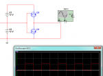
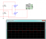
Ground has nothing to do with it

attachment.php


attachment.php
 

Attachments

  • ground1.png
    ground1.png
    26.1 KB · Views: 321
  • ground2.png
    ground2.png
    25.5 KB · Views: 337

AUS

0
Joined
Apr 12, 2012
Messages
565
Points
28
Nope, ground has nothing to do with it (unless it forms part of the circuit).

In the examples you give ground does not form part of the circuit and the osciloscope is not measuring anything with resepct to ground. Lifting the ground will not change anything (unless there is some weired control thing happening involving ground to the left off screen I can't see).

In the examples you show, the lower one is showing AC, as current flows one way through the osciloscope and then changes direction when it crosses zero, and flows in the opposite direction. The top example shows DC as current is fllowing in the same direction each time.

Does that explain it or is there something you are still unclear about? I'm assuming you understand electron flow, charge, and current. I haven't taught electronics for about 20 years so I'm a bit out of practice lol.
 

Fiddy

0
Joined
May 22, 2011
Messages
2,726
Points
63
interesting how the power ratings of switches got here lol

i can see both parts of the argument,but i think it all depends on what you are referencing to.
 
Joined
Sep 12, 2007
Messages
9,399
Points
113
I think you've misunderstood the circuit entirely.

In the examples you give ground does not form part of the circuit and the osciloscope is not measuring anything with resepct to ground.

Ground IS part of the circuit. Ground is always part of a DC circuit, although it's kind of up to you where you put it. I've changed the ground reference of the scope to another part - that is ALL that changes between the first and second circuit.

In the examples you show, the lower one is showing AC... The top example shows DC

Precisely. And yet they're the same circuit. It depends on where your ground reference is. Pulsed DC is just AC with DC added to it. If it's been a while, I suggest reading up on Fourier transform again.
 
Joined
Oct 26, 2007
Messages
5,438
Points
83
You're trying to make the case that pulsed DC isn't AC? Does the current not alternate? Do not all components in the circuit behave as if they are in an AC circuit? A square wave is still a wave, and waves are generally known to alternate.

Are you just varying your voltage from 0 to V volts? That's not AC, and a resistive load (like a lamp) will just brighten and then dim as a function of voltage, not brighten-dim-brighten as a function of the half-cycle voltage level, i.e. brighten in the "positive" cycle, dim, and then brighten again in the "negative" cycle. If you put a capacitor in series, yes, that would be AC (assuming your return is at 0 potential); however, the DC current cannot flow through a capacitor right? It would need to move back and forth to transfer power to the load.

Anyway, I don't understand what point you're trying to make here and the relationship to switches. Do you pulse your DC through a capacitor with your mechanical switch in order to mimic AC? 60 times a second? Most DC switches are responsible for step-function type transients, not something resembling AC.

If you are switching something at fast rates, switches are already designed to account for that. For example, if you're using PWM to control a motor using an H-bridge, the transistors (which are switches, albeit not mechanical) have anti-parallel diodes to prevent the back-EMF from killing things. Likewise, class-D amplifiers have diodes to prevent the large transients from affecting electronics. The effects of high DC currents and transients are real and must be accounted for in your switches.

Mechanical switching isn't done before the filter caps of DC supplies - it's done on the AC side. Besides, both a 1pF cap and a 1F cap are "capacitive loads." There is no set number you can use for this.

For some AC-DC supplies, yes, but you really can't make such blanket statements for all circuit topologies. For example, step-up DC-DC converters have reservoir capacitors at the input in order to reduce burst loads from the batteries or other DC power sources. If you have a switch in between you're switching for a capacitive load designed for high-peak currents.

In the end, if your circuit doesn't have a capacitive load, then you don't need to factor that into your switch ratings.

The cap charging in an RC circuit happens at a very low current - negligible when it comes to switches.

Again, depends on the circuit. You're stating generalities which are not qualified. Think about something such as charging a super-capacitor. Some don't even need resistors because they can handle such large surges; can your switch?

I was looking around, and the national electric code seems to think the current rating provides for incandescent lamps. I really don't think anyone in their right mind would derate a switch 80% for a light. Your typical wall switch is 10A, which means your lighting load would be limited to 240W (chandeliers are now off-limits?).

I assume you're using AC to power that chandelier? In that case the amp rating can be directly used for your lamp load--for AC. So 10A * 120V = 1200W. That sounds do-able.

Now if you're using, for some reason, a DC-powered chandelier, well then you will need to find a different switch, but good luck supplying 1200W of DC power anyway.
 
Joined
Sep 12, 2007
Messages
9,399
Points
113
however, the DC current cannot flow through a capacitor right?

Yes. A capacitor in series with pulsed DC would remove the DC component from the pulsed DC, and essentially move the whole graph down to where the average is zero.

a resistive load (like a lamp) will just brighten and then dim as a function of voltage, not brighten-dim-brighten as a function of the half-cycle voltage level, i.e. brighten in the "positive" cycle, dim, and then brighten again in the "negative" cycle.

Actually it does, but only very slightly. That's just because the filament still has heat to radiate even when no power is flowing through it. Try running a tungsten lamp on a modified sine wave inverter instead like these:

dc-ac-power-inverter-1.jpg


modified-sine-wave.jpg


and the flicker becomes noticeable because the change is more sudden. You can also notice flickering on any discharge lamp with an inductive ballast. In that case, the light output actually does go to zero when the current is zero.

I assume you're using AC to power that chandelier? In that case the amp rating can be directly used for your lamp load

I agree, but that's not what the PDF you linked says.

"voltage rating: 125VAC Lamp load multiply by 0.2-0.25"
 
Last edited:
Joined
Oct 26, 2007
Messages
5,438
Points
83
Yes. A capacitor in series with pulsed DC would remove the DC component from the pulsed DC, and essentially move the whole graph down to where the average is zero.

At which point it really isn't pulsed DC anymore is it?

Actually it does, but only very slightly. That's just because the filament still has heat to radiate even when no power is flowing through it.

That side effect isn't important to the point.

Try running a tungsten lamp on a modified sine wave inverter instead like these:

and the flicker becomes noticeable because the change is more sudden. You can also notice flickering on any discharge lamp with an inductive ballast. In that case, the light output actually does go to zero when the current is zero.

An inverter is designed to convert DC to AC. The current literally alternates, and is not just voltage-varying DC. So what is your point?

I agree, but that's not what the PDF you linked says.

"voltage rating: 125VAC Lamp load multiply by 0.2-0.25"

:confused:

Why are you comparing electrical code ratings for snap-action switches to a rerating table provided by NKK for unspecified types of switches? You do realize that different types of switches can have different properties? That ratings reflect different types of usage patterns?


I also provided that PDF as an example (as requested) of how different loads can affect the switch rating, not as the end-all-be-all table reference. Hell, maybe that table is the end-all-be-all table and that's why the estimates are so conservative. Either way, I don't know what significance you're trying to draw out here.
 
Last edited:


Top