Welcome to Laser Pointer Forums - discuss green laser pointers, blue laser pointers, and all types of lasers

LPF Donation via Stripe | LPF Donation - Other Methods

Links below open in new window

ArcticMyst Security by Avery

Question about drivers

Joined
Aug 28, 2009
Messages
37
Points
0
Yo, I'm new here. I've always loved lasers, but couldn't really afford anything >5mW. I realized that I could make my own about a week ago, and I was stoked!

Anyway, I have a 405nm diode in one of those aixiz modules. I have it wired to a driver I made and a 9v battery (i guess i'm just cheap like that.) It's working fine, as far as I can tell. I'm running it at ~100mA, but i crank it up to ~160mA with the potentiometer when i get bored...

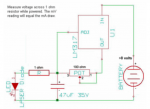
I was wondering.... Am I wrong to be using this driver I built? I'm no electronics expert, so bear with me. I'm worried because of all these complex drivers, and it seems like y'all are buying drivers instead of building 'em yourselves, even though the one i made couldn't be simpler. I have a general idea of how my driver works, but I can't be positive. I pretty much just followed the schematic, which i attached to this post. I don't see why it would be a problem, but I guess i really don't know.

I saw daedal's guide for building, like, the same driver, but with a couple other components thrown in, although i didn't know why they were needed, but then again, I barely know anything. His guide was here http://laserpointerforums.com/f42/diy-homemade-laser-diode-driver-26339.html

On another note, I was looking at pictures of drivers that were being sold, and i wasn't sure what some of the labels meant. On one of drivers, there was a point labeled as VCC"+"power and another just VCC"+". I figured one would be connected to the positive end of the power source, probably the VCC"+"power, but then what is the VCC"+" for?
On another driver, there was a label for TTL- and TTL+, and I don't know what those are for, either.
 

Attachments

  • Picture 1.png
    Picture 1.png
    173.6 KB · Views: 965
Last edited:


Joined
Jul 24, 2007
Messages
2,749
Points
0
Two years or so ago we were all building drivers like that. They tended to be too large to fit in anything other than a flashlight host.

Rkcstr and Dr Lava changed all that by designing small, reliable drivers at an affordable price.

I still make LM317 drivers if I need one in a hurry but if I need something to fit an Aixiz module I order one from here.

Regards rog8811
 
Joined
Aug 5, 2009
Messages
482
Points
28
Most likley the vcc+ are both positive inputs, one for a case positive and one normal one. each can be used as a positive input
 
Joined
Aug 28, 2009
Messages
37
Points
0
Thanks a lot. Makes sense.

I've also been looking around, but i have no idea where drlava's site is to buy his drivers, if i wanted to. Anyone know where it is?
 

seoguy

0
Joined
Feb 9, 2009
Messages
263
Points
0
You could add some additional protection if you wanted to, but the driver you constructed will work OK! :yh:

The only thing with the LM317 (as you probably have already noticed :rolleyes:), is that with your current design, nearly half of your voltage goes to heating-up the regulator, so your battery life is not going to be the greatest!

You can use a regulator that has a lower drop-out voltage, such as the LM1117 (the same one used in the rkcstr driver!), which has a maximum drop-out voltage of 1.3V. This would allow you to use a battery voltage which is closer to what your laser diode needs, thus reducing the amount of power you are wasting, and increasing battery life. :cool:

You can also use a "boost" driver, such as the Dr. Lava Flex Drive, which will allow you to use lower-voltage batteries, and boosts the voltage up to what you laser diode requires. This can be more efficient than a linear regulator, but is also a more costly option.

In addition, unlike the DDL, I don't think there is an "open-source" buck/boost regulator here at LPF - the Flex Drive is, as far as I know, a proprietary option. Although I do know of several ppl who are working hard on trying to design just such a device. :yh:

BTW, the TTL- and TTL+ are for TTL-level input digital modulation of the laser beam. TTL stands for "Transistor-Transistor Logic", and is an old standard for digital electronics, such as used by the 7400 series digital ICs, and typically utilizing a +5V power supply. By switching the TTL input between +5V and ground, you can switch the laser on and off. It can be used to digitally switch the laser on and off, for use on such things as patterns for laser light shows! :cool:
 
Joined
Aug 28, 2009
Messages
37
Points
0
Too bad the LM1117 isn't widely available, like the LM317 is :/
Out of curiousity, though, if I wanted to switch to the LM1117, it wouldn't be as simple as just switching out the 2 regulators, would it?
Also, I was wondering: if I'm supplying, say, 10v, and the diode uses 4 (that's the forward voltage... right?), then is the voltage drop across the voltage regulator 6v (not considering resistors and stuff), and are those 6 volts just released as heat? For that matter, what happens to the voltage dropped across a resistor? Is that just released as heat? I only have an EXTREMELY basic knowledge of electric circuits and stuff, I just like lasers.... a lot :p

Ya, I decided to get a DrLava flexdrive for my next laser project so that I could use a 3.6v flashlight as a host. If only they weren't out of stock everywhere!!! I guess I'll just have to wait a lil' longer...

Anyway, thanks a ton for the responses. Y'all really know your stuff! Any help is greatly appreciated.
 

seoguy

0
Joined
Feb 9, 2009
Messages
263
Points
0
Too bad the LM1117 isn't widely available, like the LM317 is :/

Digi-Key - LM1117T-ADJ-ND (Manufacturer - LM1117T-ADJ/NOPB) :yh:

Out of curiousity, though, if I wanted to switch to the LM1117, it wouldn't be as simple as just switching out the 2 regulators, would it?

Yes! I spent some time one evening squinting at circuit traces and surface mount parts in photos, sketched-out the schematic for the rkcstr driver, and was surprised to discover that, other than some extra protection parts, it was a virtually identical design to the LM317!

Also, I was wondering: if I'm supplying, say, 10v, and the diode uses 4 (that's the forward voltage... right?)

Correct.

are those 6 volts just released as heat?

Correct - that is why linear regulators are less efficient, and why you don't want the battery voltage too far away from what the diode will actually use + the drop-out voltage of the regulator.

For that matter, what happens to the voltage dropped across a resistor? Is that just released as heat?

Yep, same thing!

A fact some of the ppl recently pumping 4-4.5V into the new 3V DX green modules seem to have forgotten! :rolleyes:
 
Joined
Aug 28, 2009
Messages
37
Points
0
Ok, one more question. Maybe I should ask in the actual forum, but, how does the rectifier diode in the DDL driver protect against voltage when it's connected in parallel to the laser diode? Is it just because it only allows current in the direction opposite of the diode, so, under normal circumstances, it doesn't draw any current, but when reverse voltage is applied, it acts as a pathway to allow the current through instead of through the laser diode, which doesn't allow current through in that direction?

I've looked at DigiKey before when I was looking for parts for something else a little bit back... Is it a reliable place to get components and the like? I feel like I should make a list of everything I may need and order it all at once.

On different note, what kind of shops sell, like, raw aluminum bars for me to make crappy heatsinks with? I don't want to order online, if possible.

Y'all are really helpin' me out. I think this may be the last of my questions.
 
Last edited:


Top