Welcome to Laser Pointer Forums - discuss green laser pointers, blue laser pointers, and all types of lasers

LPF Donation via Stripe | LPF Donation - Other Methods

Links below open in new window

ArcticMyst Security by Avery

Pailide Kit Assembly.

Joined
Aug 30, 2008
Messages
6,891
Points
83
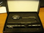
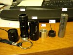
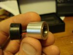
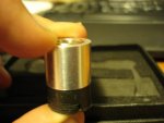
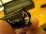
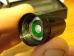
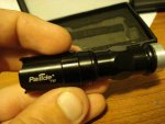
This is an assembly tutorial for the Pailide Kit i offer in the BST section (also look at my signature for a link).

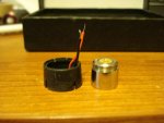
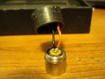
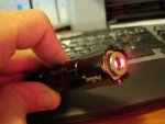
The following tutorial uses a non-functioning diode and is simply for demonstration purposes only, in case your wondering why it looks all scratched and torn up lol.


Joined
Aug 30, 2008
Messages
6,891
Points
83
Intro:
Below is a picture of what you will of received in the mail when you purchase the Pailide Kit......nice, sleek, even has it's own box.
 

Attachments

  • DSC02751.JPG
    DSC02751.JPG
    44.5 KB · Views: 144
Last edited:
Joined
Aug 30, 2008
Messages
6,891
Points
83
This is a picture of the kit when completely disassembled. Here is a list of the parts you should have.
-----------------------------------
Parts needed but not included: diode set in an aixiz module
-----------------------------------
1.Tailcap with break-away lanyard.

2.Body of flashlight. Note that the unanodized threads are meant to be screwed into the tailcap to make proper connection.

3.Head - This is where your blank PCB, Flex drive, heatsink and module will rest. Note that it screws onto the anodized side of the flashlight body.

4. Aluminum heatsink - Machined to fit the inside of the flashlight head. 12mm hole through center to hold an aixiz module, with one set screw.

5. Driver holder - This is a black cylinder which hold the blank PCB (use for battery connection) and is also where the Flex Drive is located.

6. Rechargeable 3.6v 14500 trustfire battery...used to power the kit.
 

Attachments

  • DSC02752.JPG
    DSC02752.JPG
    50.4 KB · Views: 130
Last edited:
Joined
Aug 30, 2008
Messages
6,891
Points
83
Here we have the driver holder.

Note the two wires that protrude, This is your LD and GD for your diode.
The kit will always either use a red & black, or a white & black wires. In either case, black is always your GD

Your Driver should come preset to a current of your desire, unless you requested otherwise.

Once you have determined the pin-out of your diode, Solder the wires to your diode accordingly.
 

Attachments

  • DSC02753.JPG
    DSC02753.JPG
    35.4 KB · Views: 99
Last edited:
Joined
Aug 30, 2008
Messages
6,891
Points
83
This is a picture of the flex drive Soldered to a diode.

Be sure to keep the soldering clean and quick during the solder process, and be sure you try to keep as much of the wires insulated as possible to avoid short circuiting.
 

Attachments

  • DSC02754.JPG
    DSC02754.JPG
    39.9 KB · Views: 112
Last edited:
Joined
Aug 30, 2008
Messages
6,891
Points
83
Next you want to slide your module into the heatsink.

Your module can be flush with the heatsink, this will make the lens nut recessed behind the head when screwed in all the way, offering some protection.

Your module can also be sticking out a bit, Allowing for easy focusing.

making the module flush with the heatsink seems to look the best though.

Once your decided, tighten the set screw down to hold your module in place.
 

Attachments

  • DSC02755.JPG
    DSC02755.JPG
    32.8 KB · Views: 98
Last edited:
Joined
Aug 30, 2008
Messages
6,891
Points
83
Now push the black driver holder up against the back of the heatsink so as if they are one peice.
They should go together without having to force it. If it won't let you press them together be sure to check your wires and diode pins (be sure not to bend any of your pins)

Once they are together insert the two into the head of the host untill they are inserted as far as they will go.
 

Attachments

  • DSC02760.JPG
    DSC02760.JPG
    33.4 KB · Views: 95
  • DSC02756.JPG
    DSC02756.JPG
    32.3 KB · Views: 89
  • DSC02757.JPG
    DSC02757.JPG
    36.6 KB · Views: 89
Last edited:
Joined
Aug 30, 2008
Messages
6,891
Points
83
Now screw the body onto the head.

Inserting the pieces into the head first will help prevent them from twisting while your attaching the body.

Be sure to screw the anodized side on, screwing the wrong side on will prevent proper GD connection.


Once that is done insert your battery (positive end first) into the flashlight and attach the tailcap.


Your done!
 

Attachments

  • DSC02758.JPG
    DSC02758.JPG
    42.5 KB · Views: 98
Last edited:
Joined
Aug 30, 2008
Messages
6,891
Points
83
A picture of a finished kit i took a while back.
 

Attachments

  • DSC02709.JPG
    DSC02709.JPG
    36.3 KB · Views: 120
Joined
May 12, 2009
Messages
1,403
Points
0
Excelent Tutorial, i am in the process of reviewing this host, as i currently have one in my hands, and am almost done with the review, but a review wouldnt be a review without beamshots! coming soon...

Dark


Top