

- Joined
- Nov 27, 2008
- Messages
- 65
- Points
- 8
hello,
i am a novice to building lasers and soldering. i have had this module for about a year.
i was wanting to mount this module in a small metal box as a host.
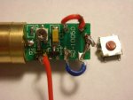
so i wanted to remove the tiny pushbutton switch on the circuit board and replace it with jumpers so i could use an external switch. i succeeded in doing this, although my soldering needs alot of improvment.
the problem is the module quit working. the diode has very little burntime on it, <2min, , i never had it on for more than 15 seconds. it is out of warranty.
my guess is it is a component in the cb gave out, or possibly a loose connection on the cb, i think this because the laser didnt go dim, it would just work sometime and quit, so i would monkey with it and then it would work.
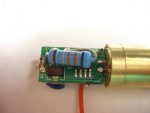
in the one pic attached, it shows a large (resistor?) with colors, brown, gold, orange, red, black on it, that had a broken solder connection which i fixed, but i noticed that when i powered up the unit, that piece got hot rather quickly. so could it be bad.
at one point, i thought it was my ground wire because it was coming loose and i have it off now, it mounts on the end of the cb, where the glob of solder is. when it had good contact then the laser would work, but i removed the wire, and touch the battery directly to the ground.
also, i was careful with the heat from the solder iron, but is it possible, i fried a component?
is it possible to troubleshoot it and replace a blown component?
i checked my jump wires with a meter, and they seem to have good connection.
i am wondering about testing the opposite end of the cb to see if the diode is getting power. if i did that, would sort of voltage is used to power a green diode?
when i did power this unit up, i was using an ultrafire 14500.
so i think this explains my situation,
any thoughts on how to test it and see what the problem is?
i am a novice to building lasers and soldering. i have had this module for about a year.
i was wanting to mount this module in a small metal box as a host.
so i wanted to remove the tiny pushbutton switch on the circuit board and replace it with jumpers so i could use an external switch. i succeeded in doing this, although my soldering needs alot of improvment.
the problem is the module quit working. the diode has very little burntime on it, <2min, , i never had it on for more than 15 seconds. it is out of warranty.
my guess is it is a component in the cb gave out, or possibly a loose connection on the cb, i think this because the laser didnt go dim, it would just work sometime and quit, so i would monkey with it and then it would work.
in the one pic attached, it shows a large (resistor?) with colors, brown, gold, orange, red, black on it, that had a broken solder connection which i fixed, but i noticed that when i powered up the unit, that piece got hot rather quickly. so could it be bad.
at one point, i thought it was my ground wire because it was coming loose and i have it off now, it mounts on the end of the cb, where the glob of solder is. when it had good contact then the laser would work, but i removed the wire, and touch the battery directly to the ground.
also, i was careful with the heat from the solder iron, but is it possible, i fried a component?
is it possible to troubleshoot it and replace a blown component?
i checked my jump wires with a meter, and they seem to have good connection.
i am wondering about testing the opposite end of the cb to see if the diode is getting power. if i did that, would sort of voltage is used to power a green diode?
when i did power this unit up, i was using an ultrafire 14500.
so i think this explains my situation,
any thoughts on how to test it and see what the problem is?
Attachments
Last edited:


