Welcome to Laser Pointer Forums - discuss green laser pointers, blue laser pointers, and all types of lasers

LPF Donation via Stripe | LPF Donation - Other Methods

Links below open in new window

ArcticMyst Security by Avery

Need help with setting current on a Driver!

Joined
Dec 18, 2008
Messages
199
Points
18
Before I begin:
Thats my first time getting into electronics , I´m pretty good in soldering and stuff but i never did anything with electronics ^^ So please be patient with me ;-]

I bought a 120mW+ Module from susie a while ago and after desoldering the button on the PCB i managed it to destroy a conducting path , dont ask me how i did that...
I wasnt able to bypass it so i got now drivers:
http://www.o-like.com/b2b_cpinfo.asp?id=987

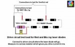
I soldered wires to the "+" and "-" and wires on the LD "+" and "-" . Then I attached a CR2 battery to the "Input" wires and my Multimeter to the LD wires. What i can get is a V reading but no mA reading ! I also turned the pot a little bit but all i get is .. nothing

So is anybody here who can help me?

Best regards
game-genie


Joined
Aug 10, 2008
Messages
268
Points
18
you need a test load to set the current properly. you can use a couple of 1N4001 diodes and a 1ohm resistor wired in parallel and read across the resistor. set you multimeter to volts or millivolts and power on. the 1ohm resistor does the math for you of converting mV => mA.
 
Joined
Dec 18, 2008
Messages
199
Points
18
I new that I forgot something >.<
Is there a way to set the current without a Testload?
But anyway thanks for your help ;-]
 
Joined
Dec 18, 2008
Messages
199
Points
18
Thanks again!
Looks like Ill make my own Test drive :-]

Best regards
game-genie
 
Joined
Dec 18, 2008
Messages
199
Points
18
I got my parts today and before I start soldering i have 2 more questions:
1. How many 1N4001 will i need?
2.With how many V must i feed the driver ( Are 3V enough?? )

Thanks again for helping a noob :D

Regards
game-genie
 
Last edited:
Joined
Jul 24, 2007
Messages
2,749
Points
0
To answer both your questions without the relavent info, I offer the following...

1) how many diodes?
Green needs 2 or 3 diodes
Red needs 4 diodes
Blu-ray needs 6 diodes

2) how many volts
Start with 5 volts then turn it down, if the laser still seems stable and as bright at 3v you can use 3v.

Regards rog8811
 
Last edited:
Joined
Dec 18, 2008
Messages
199
Points
18
Thank you rog :-D
Lets hope that i dont do anything wrong
-if it works Ill post it here
 
Joined
Dec 18, 2008
Messages
199
Points
18
Ok..
..i cant get any mV reading !
I feeding the driver with 4.8 V!
I checked the first and the second 1N4001:
The first one has : 4,45V
and the second one: 0,870V
and over the 1OHM resistor: 0,000V

Any suggestions?

Best regards
game-genie
 
Joined
Jul 24, 2007
Messages
2,749
Points
0
OK so your test load looks like this (with the correct number of diodes for the colour laser you are using.
You have soldered it to where the laser diode will be soldered onto the driver circuit when you have tested it.
You can measure a voltage across the diodes, so it looks like current is flowing.
But you say with the meter connected, as shown, set to mv you get no reading?

Is the above correct?

Regards rog8811
 

Attachments

  • test load01.jpg
    test load01.jpg
    41.2 KB · Views: 129
Joined
Dec 18, 2008
Messages
199
Points
18
I used exactly this diagram from your website to build and measure the testload!
Yes all of the above is correct i even made a second one - same thing...

Best regards
game-genie
 
Joined
Jul 24, 2007
Messages
2,749
Points
0
So on the face of it you have done nothing wrong..... Do you have another 1ohm resistor?
If so put it between the battery and the driver, doesn't matter if it is in the pos or neg line, now measure the mv across the resistor, what do you get?

Regards rog8811
200951023323735221b.jpg

Which of these pads are you using for the neg connection, suzies website doesn't seem to show it?
 
Last edited:
Joined
Dec 18, 2008
Messages
199
Points
18
I just measured the mV between Neg. Bat. input and the 1ohm resistor and got a reading , it even changed when i was turning the pot BUT it is hopping the whole time and it was far to low ( 5-180) ...

All Ive left is some Diodes and 7 1Ohm resistors...

Regards
game-genie

Ps: I´ll again double check each connection..

Edit:

http://www.o-like.com/images/UploadFile/2009510231338925.jpg this Pic shows the pos. and neg. pads.
 
Last edited:
Joined
Jul 24, 2007
Messages
2,749
Points
0
Actually ignore my question about the neg connection above, looking at the circuit layout either one will do it....

Now, you are getting current draw, but not the amount you would expect.
Please clarify, are you using a 1ohm resistor on the input?


Regards rog8811
 
Joined
Dec 18, 2008
Messages
199
Points
18
No I am not using a 1ohm resistor on the Input

Regards
game
Ps: +Rep for having patience with me ;-]
 
Last edited:
Joined
Jul 24, 2007
Messages
2,749
Points
0
I am trying to be patient but, although I aluded to it earlier you have still not even said what colour laser it is..... my guess is green, so you are going to be connecting to an IR laser diode. So your 2 diodes should be about right BUT you could try adding another one.
IR LD's run at a much lower voltage than other colours, somewhere between 1.5v and 2.5v, so with 2 1N4001'2 you are dropping 1.4v (bottom end of range)
With three 1N4001's you will be dropping 2.1v (near the top of the range)

Let me know if anything changes..

Again more info needed, If it isn't a 1ohm resistor what value is it?


Regards rog8811
 
Last edited:


Top