Trevor
0
- Joined
- Jul 17, 2009
- Messages
- 4,386
- Points
- 113
First off, this is why I write code. 
I've got a circuit built to test the beta version of OpenLPM Mk. I that uses an Ophir thermopile, but the thermopile's analog output hovers at around -6mV. So, I can't effectively measure any lasers below that. You also generally shouldn't feed negative voltage into a microcontroller. ><
It's not a huge problem, but it would definitely be nice for me to get the zero setting right.
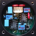
The basic design of the circuit is prettymuch a Kenometer USB that I rebuilt with Jerry's filter he posted here:
So, I've got smooth voltage coming from a +/-12V DC/DC converter into the thermopile. The output signal feeds into an Arduino.
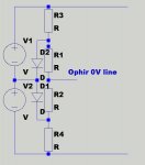
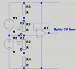
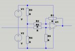
The thermopile's got four pins: +, Gnd, -, and analog out. I know to solve the negative voltage issue I've got to add a small voltage bias to the analog signal.
Could I effectively add a very high value potentiometer (1MOhm?) with the legs on the +/- voltage and the wiper pin on the analog signal so that I can add that small voltage bias? Then again, this strikes me as a situation in which the fact that voltages in parallel don't add might come into play - and I'm also not sure of the side effects of feeding that voltage into the signal line. Might it be a better plan to change the bias on the common ground pin on the thermopile?
Since I don't have a pot on hand right now, I thought it would be a good idea to ask before I made my next digikey order.
Any push in the right direction is appreciated.
-Trevor
I've got a circuit built to test the beta version of OpenLPM Mk. I that uses an Ophir thermopile, but the thermopile's analog output hovers at around -6mV. So, I can't effectively measure any lasers below that. You also generally shouldn't feed negative voltage into a microcontroller. ><
It's not a huge problem, but it would definitely be nice for me to get the zero setting right.
The basic design of the circuit is prettymuch a Kenometer USB that I rebuilt with Jerry's filter he posted here:
Got it... Thanks...
Is the MCU part number a secret... I know the FirmWare is...
The LaserBee I uses a PIC16F628A Micro Controler Unit..
No secrets there..
Looking at the drawing... now knowing where the power is coming in
and where the power is going out to the Thermopile Head Electronics...
I still see a problem... Your drawing shows absolutely no filtering on the
output of the DC/DC converter as I had suggested...:thinking:
They are Boost Converters and need filtering...IMO
When I originally scoped the input and output of the DC/DC converter
it was apparent that it was the Output and not the Input that was
the Problem with Ripple since the output of the DC/DC converter was
not filtered...
As I posted earlier I put a single 470mF electrolytic across the +12V and
ground output of the DC/DC converter and another 470mF electrolytic
across the -12V and ground of the DC/DC converter..
I have not yet had any more problems with my Lites....
But I can see requiring the Inductor coils when using a sensitive MCU..
Jerry
So, I've got smooth voltage coming from a +/-12V DC/DC converter into the thermopile. The output signal feeds into an Arduino.
The thermopile's got four pins: +, Gnd, -, and analog out. I know to solve the negative voltage issue I've got to add a small voltage bias to the analog signal.
Could I effectively add a very high value potentiometer (1MOhm?) with the legs on the +/- voltage and the wiper pin on the analog signal so that I can add that small voltage bias? Then again, this strikes me as a situation in which the fact that voltages in parallel don't add might come into play - and I'm also not sure of the side effects of feeding that voltage into the signal line. Might it be a better plan to change the bias on the common ground pin on the thermopile?
Since I don't have a pot on hand right now, I thought it would be a good idea to ask before I made my next digikey order.
Any push in the right direction is appreciated.
-Trevor