Welcome to Laser Pointer Forums - discuss green laser pointers, blue laser pointers, and all types of lasers

LPF Donation via Stripe | LPF Donation - Other Methods

Links below open in new window

ArcticMyst Security by Avery

LM317 bench test circuit

Joined
Jul 24, 2007
Messages
2,749
Points
0
I am seeing a number of posts where builders have tried to do all the right things when testing LD's on a proper drive circuit....and then failing by forgetting to short out the capacitor before connecting the LD.

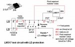
Here is an idea for you...... I have a circuit that I do all of my testing on, it is always knocking around on my workbench should a sudden laser check be required. What makes it different from the circuits I make for final build is that it has:-

A 2 way terminal block for connecting the flying leads from the LD
A series of test points for connecting up the multi meter
And most importantly...
A double pole, single toggle (change over) switch to short out the capacitor and turn off the power

It does what it says, when you turn off the power you short out the capacitor, which means you can safely connect/disconnect LD's without zapping them with the contents of the capacitor.

I hope that helps....

Regards rog8811
 

Attachments

  • LM317_test_circuit_001.jpg
    LM317_test_circuit_001.jpg
    113.2 KB · Views: 7,677


Zom-B

0
Joined
Mar 25, 2008
Messages
895
Points
28
Very good idea. Maybe you should have labeled the test points an then stated, measure the current between C and D and voltage between D and E and so on.

I use a graphical transistor tester for my LD testing. (looks something like an oscilloscope but it traces a voltage/current graph of whatever is under test, and it's power-limited so it wont easily blow a LD.
 
Joined
Jul 24, 2007
Messages
2,749
Points
0
Very good idea. Maybe you should have labeled the test points an then stated, measure the current between C and D and voltage between D and E and so on.

Done, thanks for the suggestion.

I use a graphical transistor tester for my LD testing

DROOOOOOOL :p
 

Zom-B

0
Joined
Mar 25, 2008
Messages
895
Points
28
Back on topic, It would be nice if you could build these drivers for other forum members who are a noob at electronics.
 
Joined
Jul 24, 2007
Messages
2,749
Points
0
I think DDL made some dual LM317 adjustable drivers about a year ago, I don't think it had the shorting switch... maybe he will do some more some time...and it is time, lack of, that prevents me from considering it.
The thing is that this is a good starting project for anyone wanting to make lasers, it doesn't have to be small, with all the test points it is easy to make sure it works before adding an LD....

Regards rog8811
 
Joined
May 17, 2008
Messages
44
Points
0
One thing I don't get.

If the capacitor is charged up to a voltage which corresponds to the correct current for the laser diode, seems as it was tested at that current, why would the charge damage the laser diode ?
 
Joined
Oct 26, 2007
Messages
5,438
Points
83
Here's basically how it works: we keep a capacitor in parallel with the load (the laser) in order to allow current spikes to pass through the capacitor intead of the laser; the current kills the diode, not so much the voltage. The capacitor also slows the rise in voltage level as the capacitor charges to the full potential.

So say we were to turn off the powering circuit and at the same time yank off the laser, and let's assume we don't need to worry that doing so will hurt it. Assuming the capacitor is still charged up, what will happen to the charge? Well it'll just stay on that capacitor, slowly bleeding off.

What happens if you connect the laser back up without discharging the capacitor?? Being charged, the capacitor will act like a small battery, and connecting the laser diode between the terminals will allow current to flow. Since there isn't another capacitor to charge, all that current will go through the laser diode, frying it.

Also note that capacitors can gain charge through just sitting around in the air. Some large powerline capacitors must remain shorted or they can kill people who touch them.
 
Joined
May 17, 2008
Messages
44
Points
0
But due to the forward voltage of the laser diode and the resistance of the 1Ohm resistor, the current will be limited.
Due to these two things, we can directly link voltage and current.

The capacitor's voltage would never be more than the regulator is supplying, which due to the relationship I stated above is fixed (Only aproximatly, thanks to temperature.) by the current flowing through the laser diode.

For this reason, I still don't see how (As long as the resistor is there.) the current can be any higher than the current the regulator was supplying.

Am I missing something here ?

Also, it might be advisable to add a bleeder resistor across the capacitor, if the charge in it does damage the laser diodes. If this is done, don't forget to compensate for current "lost" through the bleeder resistor. Remember that the capacitor will discharge to 1/3 of it's charge (IIRC) in the following time:

T = 1.1 * R * C

Where T is the time in seconds.
R is the resistance in ohms.
C is the capacitance in farads. (Note: Farads, not microfarads.)
 
Joined
Jul 24, 2007
Messages
2,749
Points
0
I typed up all sorts of answers to yngndrw's post but discovered that I don't know enough about electronics ::)
I will just say that there have been many threads where it appears that the most likely cause of LD death was a capacitor discharging through the LD..... I just offer this test circuit up as a way of safe connection/deconnection...it works for me.

The circuit now sports a red LED to let me know the supply is on and a green LED to let me know the output is off and the capacitor shorted.

Regards rog8811
 

phenol

0
Joined
Oct 30, 2007
Messages
533
Points
18
well, if the diode is disconnected (on the event of intermittent connections or abstracted operators) from the regulator while the latter is turned on, the only thing that remains on its output is the capacitor. In its futile attempt to keep the current steady, the regulator linearly increases the voltage across the capacitor to whatever level it can (in the case of LM317 - to almost Vcc, in some switching mode drivers - to tens of volts or til smth blows, usually the regulator itself (unless its output is protected against load disconnect)). Suppose Vcc=6V and the red LD has a poorly soldered rattling wire to it. If the wire loses contact with the load (diode), the voltage would rise up in a short time to..say...5.7V Once contact is restored, the cap dumps its charge into the LD, forcing a powerful spike thru it, till the regulator is regulating again and the current is what it is designed to be...but too late.
 
Joined
May 17, 2008
Messages
44
Points
0
Well you can't really beat real world experiance. Sometimes things don't quite happen how they "should", or how we'd expect them to.

I'm just throwing these questions around for two reasons:
1) Some things just don't add up to me, so for my benefit I'd like to know what i'm doing wrong.
2) There might be an underlying problem which is causing these deaths. E.g. Static discharge when removing the laser diode.

Edit: Missed Phenol's reply.
Ah, I was missing the point. There's only a problem if the laser diode is disconnected while the supply is on. (I thought the problem was while it was off.)

That makes more sense now, thanks.
 
Joined
Jan 7, 2007
Messages
6,309
Points
83
Very many years ago, we added a "bleeder" resistor across the capacitor. A couple mA will drain the cap in a few seconds.
This is the "old school" way. KISS :D

Mike
 
Joined
Oct 26, 2007
Messages
5,438
Points
83
The current passing through a capacitor is defined as:

i(t) = C * dv(t)/dt

Where i(t) is the current over time, C is the capacitance of the capacitor, and dv(t)/dt is the change in voltage over time.

Any sudden change in the voltage for the capacitor, like adding in a laser diode which provides a voltage drop and a current path to ground, will cause a spike in the current. If you shut off the regulator, the pins on it generally "float" so the charge remains on the capacitor; adding the diode will provide a current path for the capacitor to discharge through.
 
Joined
Jan 20, 2008
Messages
1,724
Points
0
Nice circuit, it certainly helps prevent one specific type of failure... However, I'm thinking it also introduces another point of failure: the terminal block. If you're plugging the LD into some sort of socket rather than soldering it in place you run the risk of having it disconnect and reconnect at inopportune times, giving it the full force of that pesky capacitor.
 
Joined
Jul 24, 2007
Messages
2,749
Points
0
If you're plugging the LD into some sort of socket rather than soldering it in place you run the risk of having it disconnect and reconnect at inopportune times, giving it the full force of that pesky capacitor.
A valid point but I have seen horendous photo's on here with the LD connected with croc clips or twisted wires, at least with a good terminal block there is less chance of accidental disconnection.

Regards rog8811


Top