- Joined
- May 24, 2009
- Messages
- 53
- Points
- 8
Looking to build my own drivers for open can red and phr-803t's
Options to power driver with:
(3) Ultra Fire 10440 3.6V in
(3) 1.2v AAA
My driver choice is the LM1117mpx-adj so i can use it for both diodes.
Question 1- would it be better to use the 3.6v parrallel or in series at
10.8v.
I know the voltage varies as fully charged and when its discharging so keeping the supply voltage above the requirments of the diode +1.2v "required by the driver" as long as possible would be best since this is not a boost curcuit. As long as you dont exceed component capabilities.
Im not sure if 10.8v input produces more heat or not as compared to the 3.6v input that would quickly drop below voltage requirements.
here is a quick post on the lm117:
worst case senario i figured batteries in series 10.8v for phr-803t
and parallel 3.6v for lpc-815.
if you can suggest another battery option for red can diode please do.
Question 2: How do i limit current.
since i use this as a voltage regulator could i use a resistor to limit current to the diode. would that be a larger value before the regulator or smaller value after ?
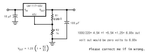
this is what i got:
Any help is appreciated.:thanks:
Options to power driver with:
(3) Ultra Fire 10440 3.6V in
(3) 1.2v AAA
My driver choice is the LM1117mpx-adj so i can use it for both diodes.
Question 1- would it be better to use the 3.6v parrallel or in series at
10.8v.
I know the voltage varies as fully charged and when its discharging so keeping the supply voltage above the requirments of the diode +1.2v "required by the driver" as long as possible would be best since this is not a boost curcuit. As long as you dont exceed component capabilities.
Im not sure if 10.8v input produces more heat or not as compared to the 3.6v input that would quickly drop below voltage requirements.
here is a quick post on the lm117:
The LM1117 is a series of low dropout voltage regulators
with a dropout of 1.2V at 800mA of load current. It has the
same pin-out as National Semiconductor’s industry standard
LM317.
The LM1117 is available in an adjustable version, which can
set the output voltage from 1.25V to 13.8V with only two
external resistors. In addition, it is also available in five fixed
voltages, 1.8V, 2.5V, 2.85V, 3.3V, and 5V.
The LM1117 offers current limiting and thermal shutdown. Its
circuit includes a zener trimmed bandgap reference to assure
output voltage accuracy to within ±1%.with a dropout of 1.2V at 800mA of load current. It has the
same pin-out as National Semiconductor’s industry standard
LM317.
The LM1117 is available in an adjustable version, which can
set the output voltage from 1.25V to 13.8V with only two
external resistors. In addition, it is also available in five fixed
voltages, 1.8V, 2.5V, 2.85V, 3.3V, and 5V.
The LM1117 offers current limiting and thermal shutdown. Its
circuit includes a zener trimmed bandgap reference to assure
worst case senario i figured batteries in series 10.8v for phr-803t
and parallel 3.6v for lpc-815.
if you can suggest another battery option for red can diode please do.
Question 2: How do i limit current.
since i use this as a voltage regulator could i use a resistor to limit current to the diode. would that be a larger value before the regulator or smaller value after ?
this is what i got:
Any help is appreciated.:thanks:


") will keep posted on progress.
will keep posted on progress.