Welcome to Laser Pointer Forums - discuss green laser pointers, blue laser pointers, and all types of lasers

LPF Donation via Stripe | LPF Donation - Other Methods

Links below open in new window

ArcticMyst Security by Avery

laser not turning on

Zak

0
Joined
May 8, 2013
Messages
24
Points
0
Hi guys

so i was in the process of my first build and then i ran into a problem. my laser wouldn't turn on!.

Here's the stuff i have:

9mm laser from dtr with a G2 lens in a module
1.8A lazeerer X-drive V6 driver
2x panasonic 18650's 3.7V each
and a switch.

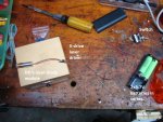
so here is how everything is connected.
1st the two batteries are put in series.
2nd the positive terminal from the batteries travels to my switch
3rd the negative terminal/Gnd travels to the X-drive V- terminal.
4th the negative terminal/Gnd from the laser diode travels to the LD- terminal
5th the other end of the switch travels to the X-drive V+ terminal
6th finally the postive terminal of the laser diode travels to the LD+ terminal

I think everything is correctly attached. Attached is also a picture of the setup(sorry for the mess).


so i did some experimentation with a multi meter. first i measured the voltage at the input of the driver after the switch and i was measuring 7.3-7.4V due to the series combination of the lithium ion batteries in series. so this was correct both my batteries and switch were working.

Then i measured the voltage at the output of the driver( connected to the laser) but i was measuring 0 volts. Then i removed the laser and measured the output voltage and it was still 0 volts. Then i added a 40 ohms resistor and still 0 volts. I dont think my driver that i just bought should be giving me 0 volts at the output when i feed in 7.4V volts.

so i was wondering if you guys think this is a driver issue or the laser is dead. I am thinking of using a simple LM317 circuit (like the one here: https://www.youtube.com/watch?v=2Rjlf7gnXms ) and connect it to the diode to see if it is operational since i have never turned it on before.

looking forward to your reply
Zak
 

Attachments

  • DSC02339.jpg
    DSC02339.jpg
    137.5 KB · Views: 186
Last edited:


Joined
May 14, 2013
Messages
3,438
Points
0
It sure sounds like a driver issue, are you sure you didn't connect it backwards or something? Also you shouldn't power on that module at 1.8A unless you put it in some kind of heat sink because it will overheat in just seconds.
 

Zak

0
Joined
May 8, 2013
Messages
24
Points
0
yep completely sure it is soldered on correctly. with regards to heatsinking, i actually have a blue heat sink that is placed behind the box as shown in the image. i will definitely put it on.

To me to sounds like a shame that the new driver is not operational. I just got it today and was so happy to put everything together and then there was no light in the end.

Do you think it would be a good idea to atleast see if the laser is still operational, i have just ordered a LM317 regulator and intend to hook up a 10 ohm resistor to draw a current of 125mA to ensure that the laser is fine.

If the laser is fine then i will begin else where to look for high current buck drivers but i dont know anyone else that provide drivers which supply around 2A current apart from lazereer.
 
Joined
May 14, 2013
Messages
3,438
Points
0
Do you think it would be a good idea to atleast see if the laser is still operational, i have just ordered a LM317 regulator and intend to hook up a 10 ohm resistor to draw a current of 125mA to ensure that the laser is fine.

If the laser is fine then i will begin else where to look for high current buck drivers but i dont know anyone else that provide drivers which supply around 2A current apart from lazereer.

I believe that 9mm needs more than 150ma to power it on, try two 10 ohm in parallel or a 5 ohm or even less, you can go as low as 1 ohm and get up to 1.5A from a LM317.

There are many places to buy drivers.
Cajunlasers Store
Survival Laser USA Home
http://www.aixiz.com/
and others or maybe you can make your own. Are you planning a hand held or a labby?

Alan
 

Zak

0
Joined
May 8, 2013
Messages
24
Points
0
ok i might try to draw 1 amp out of it and see what happens.

Thanks
 
Joined
Feb 5, 2008
Messages
6,252
Points
83
You said that at one point you tried measuring the voltage of the driver with no load connected on it's output. If this is a switching driver, it's definitely dead.

NEVER run a driver without a soldered load. Not alligator clipped load. Voltmeter isn't a load, and ampmeter is a short circuit, basically.
 

Zak

0
Joined
May 8, 2013
Messages
24
Points
0
yes i did try measuring the voltage of the driver with no load connected on its output. yes it is a switching driver, which i say switch i mean a buck regulator. I ran several buck regulators on their own with no load attached in the past to measure the ripple voltage at the output. I see no need for the driver to die with no load attached. As i have done previously when designing power supplies.

In this particular case I believe the driver itself was bad to begin with.
 
Last edited:
Joined
Feb 5, 2008
Messages
6,252
Points
83
yes i did try measuring the voltage of the driver with no load connected on its output. yes it is a switching driver, which i say switch i mean a buck regulator. I ran several buck regulators on their own with no load attached in the past to measure the ripple voltage at the output. I see no need for the driver to die with no load attached. As i have done previously when designing power supplies.

In this particular case I believe the driver itself was bad to begin with.
That of course remains the strongest possibility - I'm just naming some other things to be careful about.

Running with no load on output is 100% fatal for boost drivers with no open load protection, though. If buck drivers do survive, it's great, but I wouldn't risk it normally.
 

Zak

0
Joined
May 8, 2013
Messages
24
Points
0
ok thanks for the advice i will remeber not to do this in the future.
 
Joined
Aug 7, 2010
Messages
2,086
Points
0
yes i did try measuring the voltage of the driver with no load connected on its output. yes it is a switching driver, which i say switch i mean a buck regulator. I ran several buck regulators on their own with no load attached in the past to measure the ripple voltage at the output. I see no need for the driver to die with no load attached. As i have done previously when designing power supplies.

In this particular case I believe the driver itself was bad to begin with.

Hehe! You're talking about constant voltage power supplies. Thats why they won't die.

One should use constant current "power supplies" for lasers. Thats why they goes damaged. A switching, constant current driver without a load connected, turned on, dies. Unless it has some kind of protection.

You should try test-load test for your driver.
 
Last edited:

Zak

0
Joined
May 8, 2013
Messages
24
Points
0
ok so the LM317's arrived today and set everything up . Then I turned on my power supply and YES! the laser is fine. woooo!. I set the resistor to draw a current of 600mA and it was burning through cardboard. However I intead to run it at 2000mA. so i need to buy another driver!

I looked at the places that Alan had offered and here is what i found

Cajunlasers Store: this is where i bought my laser driver and it came in faulty and they dont offer 2A switching drivers anymore
Survival Laser USA Home: They do offer a current output of 1.8A switching driver so i might ask them if can offer one at 2A
http://www.aixiz.com/ : they dont really offer a switching driver

maybe you can make your own:
I could make my own but drivers are cheap and so i see no need for me to:
1.design a circuit
2.test it
3.then design my PCB
4.wait for the manufacture time
5.assemble it
6.then finally use it

but i guess if i cant find a switching driver rated at 2A then i will end up having build one.

If anyone has a working switching driver the delivers an output current of 2A then contact me.

Zak
 
Joined
Aug 7, 2010
Messages
2,086
Points
0
You can go as high as 1.5A on the LM317 driver. Just wire some resistors as 0.8ohm and make sure to heatsink the IC well...
A good bet is to source the LM317 only the voltage it need, found by Diode forward voltage + LM317 dropout (around 2,5V for 1.5A out).

ie don't feed the lm317 with 12v, 24v, as it will only dispense extra energy as heat.

:beer:


Top