anderp
0
- Joined
- May 17, 2015
- Messages
- 27
- Points
- 3
Hi all!
I recently purchased a number of different bits and pieces and assembled my first self-built custom lasers out of two Kryton Groove hosts.
One with a Oclaro HL63133DG 638nm diode, a V5 FlexDrive @ 300mA, and a three-element lens (the divergence is AMAZING on this one, and such a nice red!)
And the other with an M462 462nm diode, one of (formerly known as Le Quack) Hiemal's Super BoostDrives @ 1.75A, also with a three-element lens.
Both are running off single nice fresh protected Panasonic NCR18650Bs.
I of course got the hosts from grainde, with matching cyan/red GITD (and even a blue tailcap for the M462) and with contact boards pre-fitted / tailcaps pre-assembled.
Here I ran into an issue. I spent almost 20 minutes trying to work out why my Super BoostDrive was working fine off my bench power supply, but would have nothing to do with operating off the battery in the host, only to discover that the tailswitch wasn't actually closing the circuit.
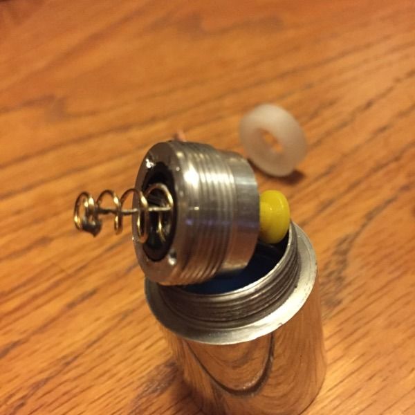
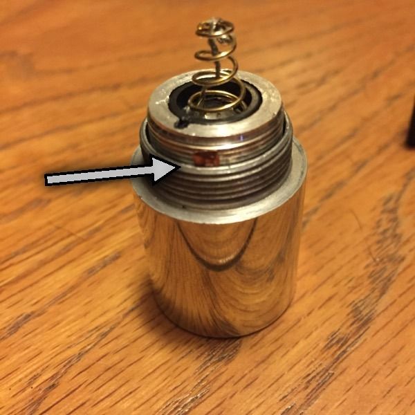
The tailswitch assembly slides around inside the tailcap and fails to make proper contact with the tailcap walls - it also seems to have some issues making proper contact with its spring.
With enough prodding and poking to get the mechanism into the right position, I can convince the lasers to work (and oh boy are they pretty when they work), but for the most part they just don't get power.
Is there something I should have done / should do to the tailcap assembly to get it to co-operate? Is there perhaps a better tailswitch assembly I can use? Even at the best of times this one seems to be annoyingly high resistance (0.2-0.3 ohms typical, sometimes 0.1), which is not optimal for the high current draw of the Super BoostDrive.
I've PMed grainde, of course, but I figured it couldn't hurt to ask if anyone else has had similar issues (I tried a search but didn't get very far... you know how vBulletin search is).
In the immortal words of various internet people; What do? How fix?
Oh, one other thing - am I meant to have an o-ring for the focus ring / lens holder?
Last edited:


