Garoq
0
- Joined
- Aug 27, 2010
- Messages
- 1,525
- Points
- 83
There has been some discussion and controversy recently about this very popular buck driver for 445nm diodes, many have enjoyed repeated success but some have experienced difficulties. The driver has been widely used in lasers built with the C6, S4, Survival Laser Stainless Steel and other similar hosts.
An "Analysis of Electrical Performance" of this driver may be downloaded here in PDF format.
First of all, this is a buck-type driver that uses the AX2002 switching controller. It can handle a wide range of input voltage and can be modified to output from less than 100mA to over 1.8A. In this schematic, the 'R2' resistor controls the output current:
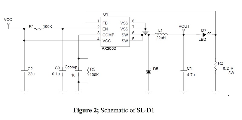
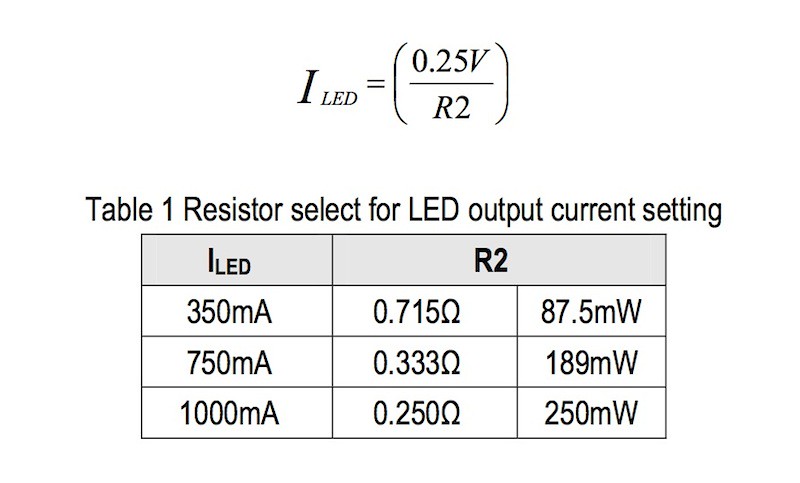
And this equation allows you to calculate the value of R2 based on the desired output current:
However, driver current modification is not the purpose of this post. The purpose of this tutorial is to provide a step by step explanation of how to install, test and use the stock driver properly and avoid the problems that some have experienced.
The driver appears to be very well designed except for one issue. One of the pads for the output current setting "R2" resistor is placed extremely close to the edge of the board and is prone to shorting out against the brass ring when assembled (this is the resistor marked "R200" in the photo below). The usual result of this shorting is that the driver will fail and not produce any current at all. I have experienced about a 15% failure rate if the driver is soldered to the brass ring without any prior preparation.
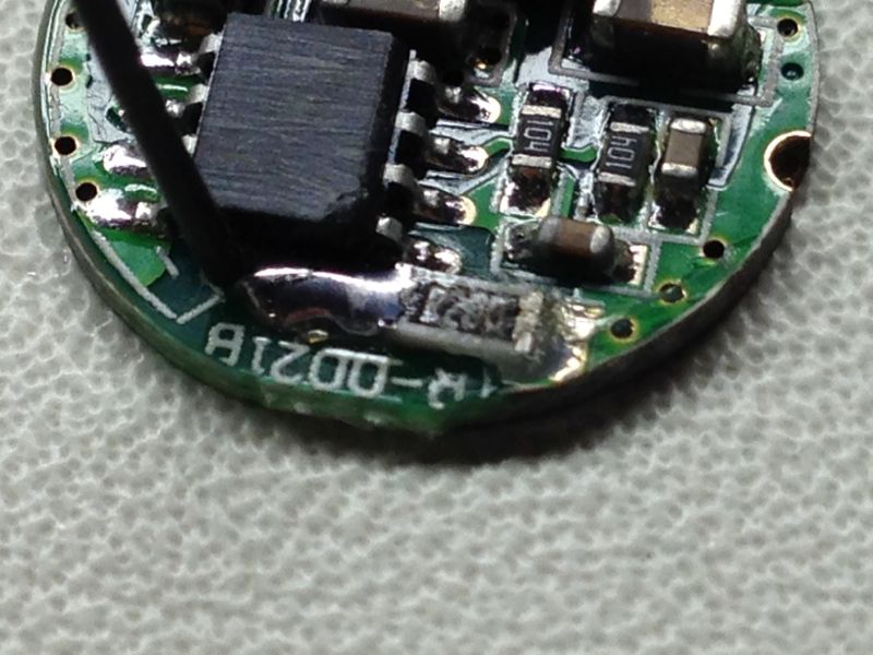
To combat this failure rate, I apply a small dab of silicone caulk to the exposed R2 resistor pad and allow it to harden before proceeding with assembly. All the SL-SD-1 drivers sold by Survival Laser have this silicone applied, and we also perform regular lot acceptance testing on the drivers we receive.
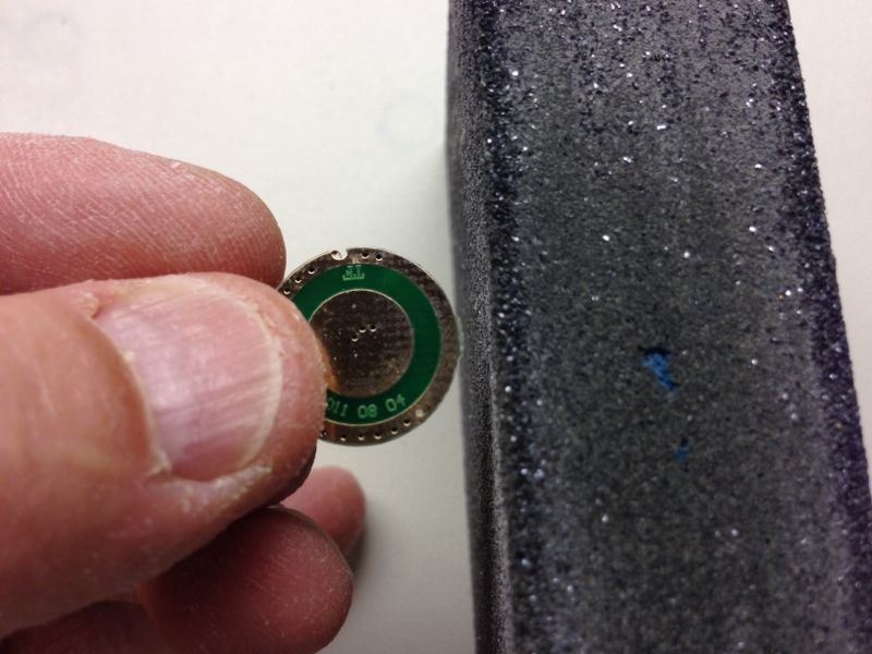
So, let's begin the tutorial. First, remove the nubs from the sides of the driver board with sandpaper or a small file:
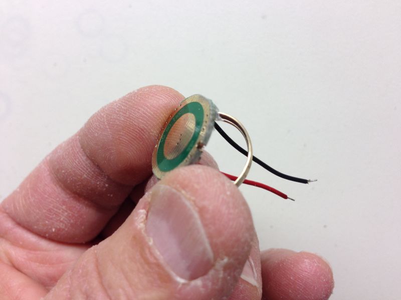
Optionally, you may want to replace the short, stiff stock wires with FP's silicone insulated wire before proceeding.")
Next, insert the board, component side first, into the side of the brass ring with the recess:
Push the driver board completely into the recess in the ring:

NOTE: When soldering a driver to a brass ring, apply the solder very sparingly and be extremely careful not to let the solder flow under the ring and onto the component area of the driver board. If the solder flows onto the component side, it can render the driver non-functional and may even damage your diode when used.
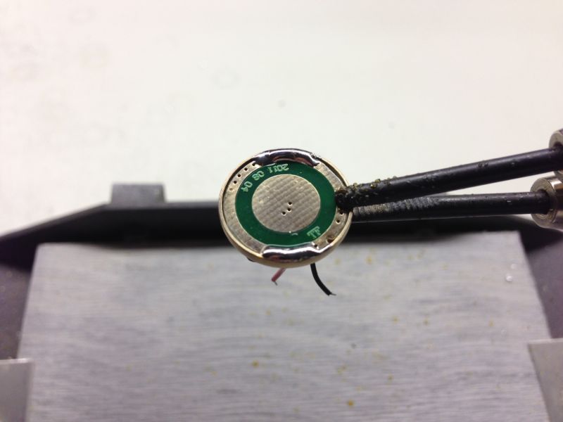
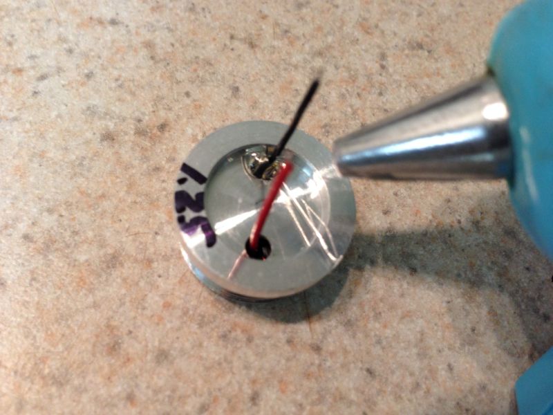
Solder a small spot on the negative board trace next to the brass ring about 1/4" wide. Ensure that the solder has wetted both the board and the ring:
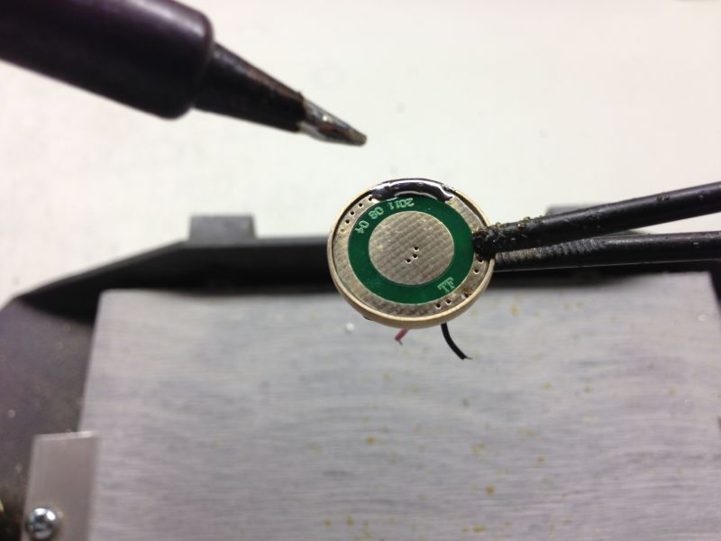
Solder a similar spot on the board 180 degrees from the first spot:
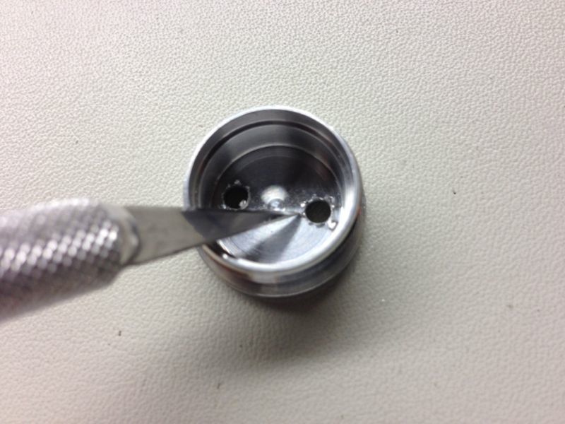
Before installing the driver subassembly in the pill, remove any loose chips in the pill remaining from the drilling process using a knife or a small steel ruler:
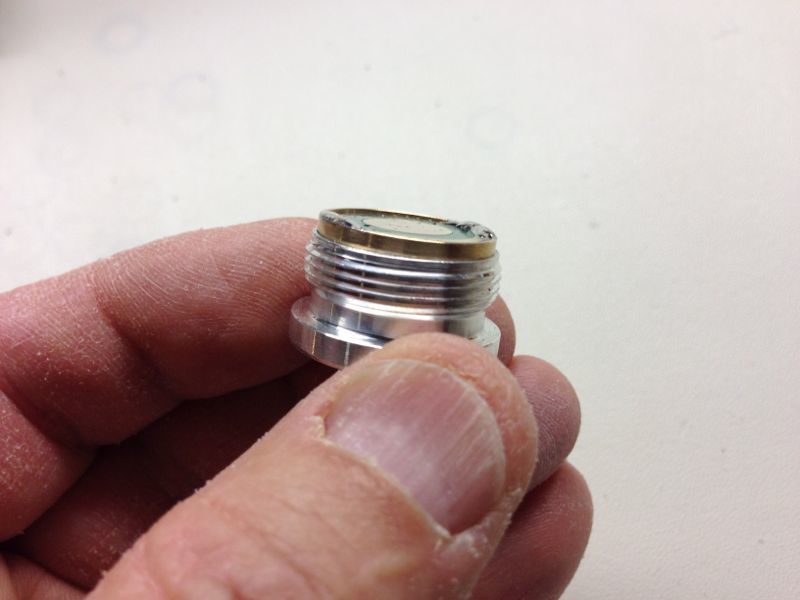
Place the brass ring & driver subassembly, tapered side first, into the recess in the pill, while threading the driver wires through the holes in the pill:
Lightly press the brass ring & driver subassembly into the pill recess until is evenly spaced above the pill:
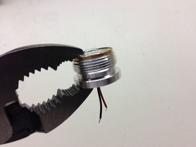
Using pliers, gently squeeze the brass ring & driver subassembly into the pill recess. Work your way around the pill to push the ring evenly and completely into the pill:
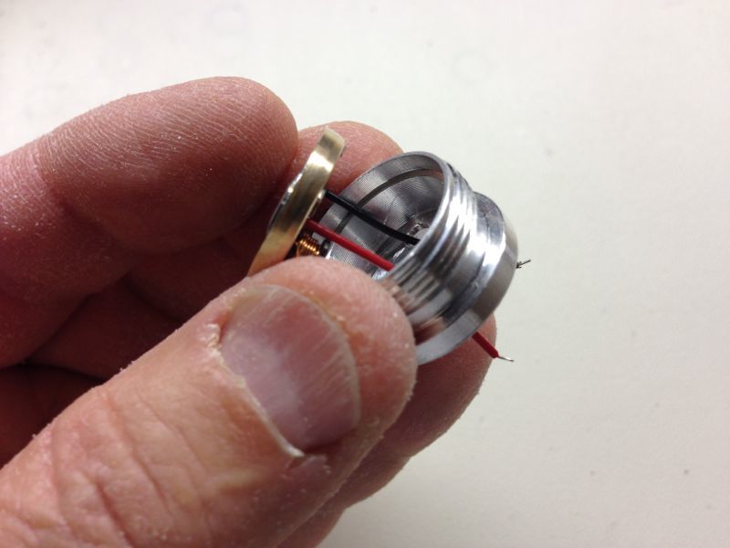
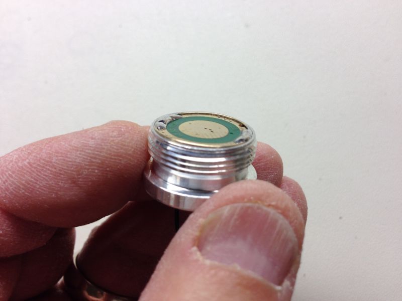
Side view of the completed assembly:
The driver and pill assembly is finished. Now the most important part: testing. You should never connect an untested driver or driver assembly to a diode, as you may risk losing the diode if the driver isn't outputting the proper current. Install the completed driver and pill module in your host and attach it to a selectable test load and DMM to measure the current output. Set the test load at 4 diodes for this driver. After the connections are made, install two 16340 or 18650 batteries in the host, screw on the tail cap and turn the unit on. Your DMM should indicate approximately 1.25A, although the normal range of output from this driver is 1.20 to 1.27A.
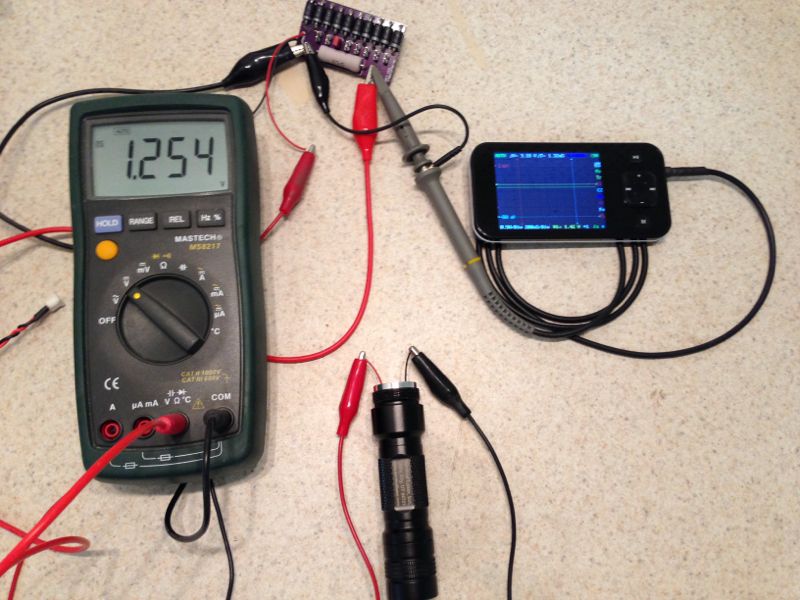
Shut the unit off, remove the batteries and disconnect from the test load. Never allow the driver to operate without a test load or diode attached.
Optionally, especially if you are using the stock driver wires, it may be helpful to apply some strain relief in the form of silicone or hot melt glue to the holes where the wires exit the pill:
You are now ready to connect the driver and pill assembly to your diode. I've posted a tutorial here about soldering a driver and pill assembly to a diode. Before attaching to your diode, be sure to touch the output wires together briefly to remove any possible remaining charge in the circuit.
Enjoy! :beer:
An "Analysis of Electrical Performance" of this driver may be downloaded here in PDF format.
First of all, this is a buck-type driver that uses the AX2002 switching controller. It can handle a wide range of input voltage and can be modified to output from less than 100mA to over 1.8A. In this schematic, the 'R2' resistor controls the output current:
And this equation allows you to calculate the value of R2 based on the desired output current:
However, driver current modification is not the purpose of this post. The purpose of this tutorial is to provide a step by step explanation of how to install, test and use the stock driver properly and avoid the problems that some have experienced.
The driver appears to be very well designed except for one issue. One of the pads for the output current setting "R2" resistor is placed extremely close to the edge of the board and is prone to shorting out against the brass ring when assembled (this is the resistor marked "R200" in the photo below). The usual result of this shorting is that the driver will fail and not produce any current at all. I have experienced about a 15% failure rate if the driver is soldered to the brass ring without any prior preparation.
To combat this failure rate, I apply a small dab of silicone caulk to the exposed R2 resistor pad and allow it to harden before proceeding with assembly. All the SL-SD-1 drivers sold by Survival Laser have this silicone applied, and we also perform regular lot acceptance testing on the drivers we receive.
So, let's begin the tutorial. First, remove the nubs from the sides of the driver board with sandpaper or a small file:
Optionally, you may want to replace the short, stiff stock wires with FP's silicone insulated wire before proceeding.
Next, insert the board, component side first, into the side of the brass ring with the recess:
Push the driver board completely into the recess in the ring:
NOTE: When soldering a driver to a brass ring, apply the solder very sparingly and be extremely careful not to let the solder flow under the ring and onto the component area of the driver board. If the solder flows onto the component side, it can render the driver non-functional and may even damage your diode when used.
Solder a small spot on the negative board trace next to the brass ring about 1/4" wide. Ensure that the solder has wetted both the board and the ring:
Solder a similar spot on the board 180 degrees from the first spot:
Before installing the driver subassembly in the pill, remove any loose chips in the pill remaining from the drilling process using a knife or a small steel ruler:
Place the brass ring & driver subassembly, tapered side first, into the recess in the pill, while threading the driver wires through the holes in the pill:
Lightly press the brass ring & driver subassembly into the pill recess until is evenly spaced above the pill:
Using pliers, gently squeeze the brass ring & driver subassembly into the pill recess. Work your way around the pill to push the ring evenly and completely into the pill:
Side view of the completed assembly:
The driver and pill assembly is finished. Now the most important part: testing. You should never connect an untested driver or driver assembly to a diode, as you may risk losing the diode if the driver isn't outputting the proper current. Install the completed driver and pill module in your host and attach it to a selectable test load and DMM to measure the current output. Set the test load at 4 diodes for this driver. After the connections are made, install two 16340 or 18650 batteries in the host, screw on the tail cap and turn the unit on. Your DMM should indicate approximately 1.25A, although the normal range of output from this driver is 1.20 to 1.27A.
Shut the unit off, remove the batteries and disconnect from the test load. Never allow the driver to operate without a test load or diode attached.
Optionally, especially if you are using the stock driver wires, it may be helpful to apply some strain relief in the form of silicone or hot melt glue to the holes where the wires exit the pill:
You are now ready to connect the driver and pill assembly to your diode. I've posted a tutorial here about soldering a driver and pill assembly to a diode. Before attaching to your diode, be sure to touch the output wires together briefly to remove any possible remaining charge in the circuit.
Enjoy! :beer:
Last edited: