

Garoq
0
- Joined
- Aug 27, 2010
- Messages
- 1,525
- Points
- 83
This is a quick tutorial on how to install one of our blank battery contact boards in a drilled C6 pill.
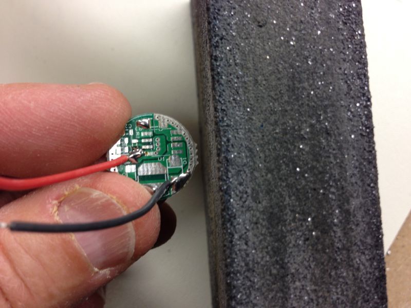
First, remove the nubs from the sides of the board with sandpaper or a small file:
Next, insert the board, wire side first, into the side of the brass ring with the recess:
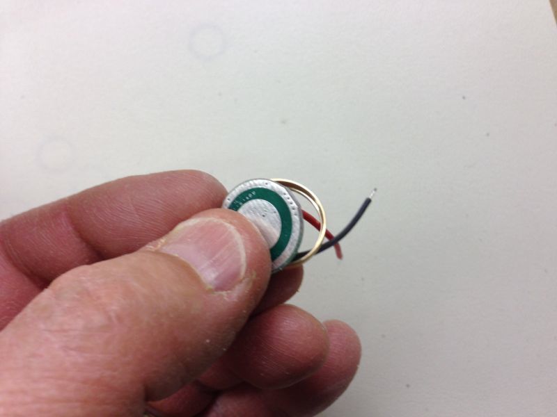
Push the driver board completely into the recess in the ring:
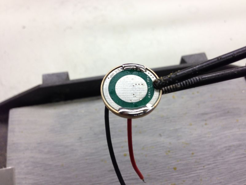
Solder a small spot on the negative board trace next to the brass ring about 1/4" wide. Ensure that the solder has wetted both the board and the ring:
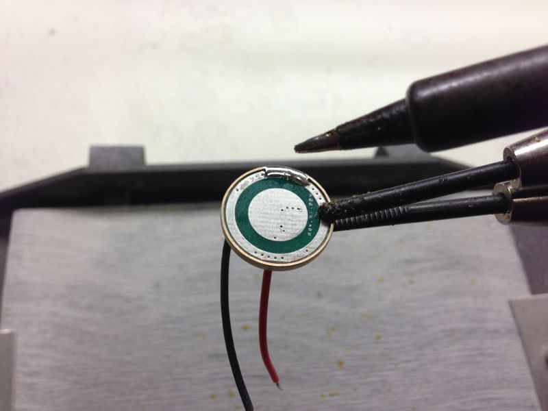
Solder a similar spot on the board 180 degrees from the first spot:
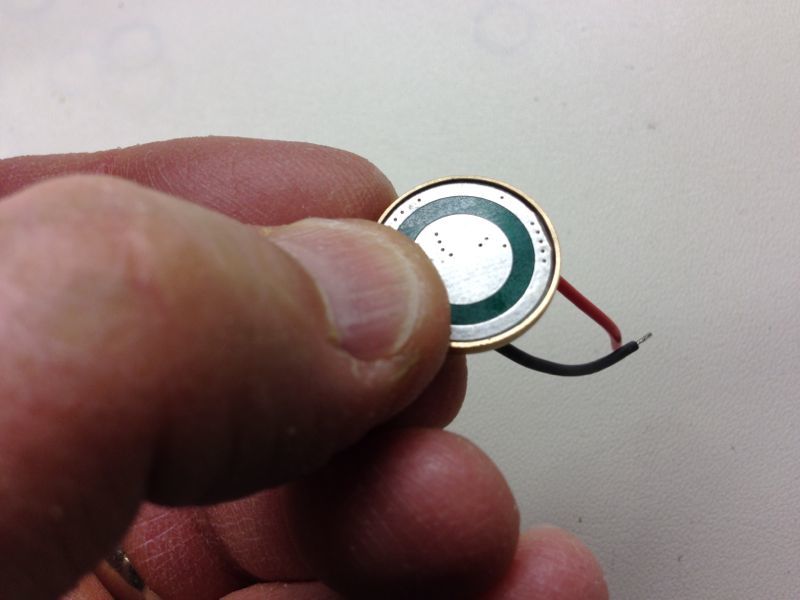
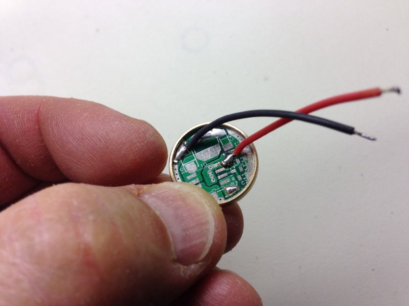
Wire side view of the finished subassembly:
Place the brass ring & board subassembly, tapered side first, into the recess in the pill:
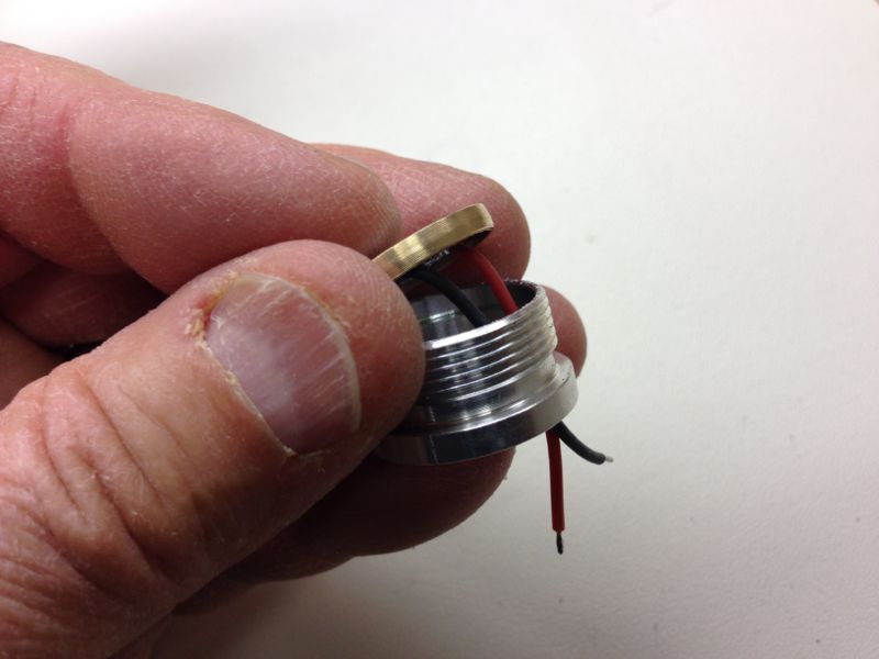
Lightly press the brass ring & board subassembly into the pill recess until is evenly spaced above the pill:
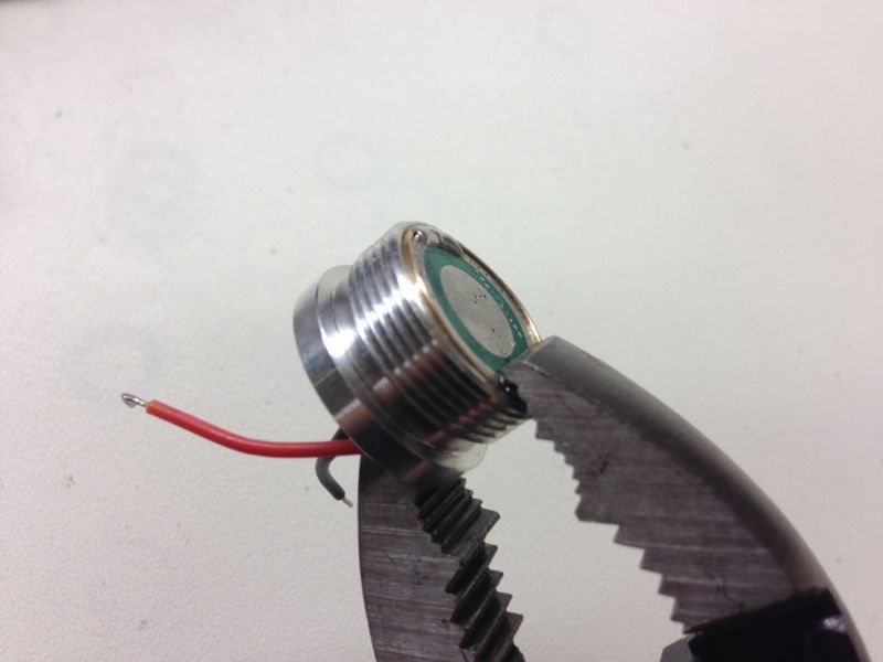
Using pliers, gently squeeze the brass ring & board subassembly into the pill recess. Work your way around the pill to push the ring evenly and completely into the pill:
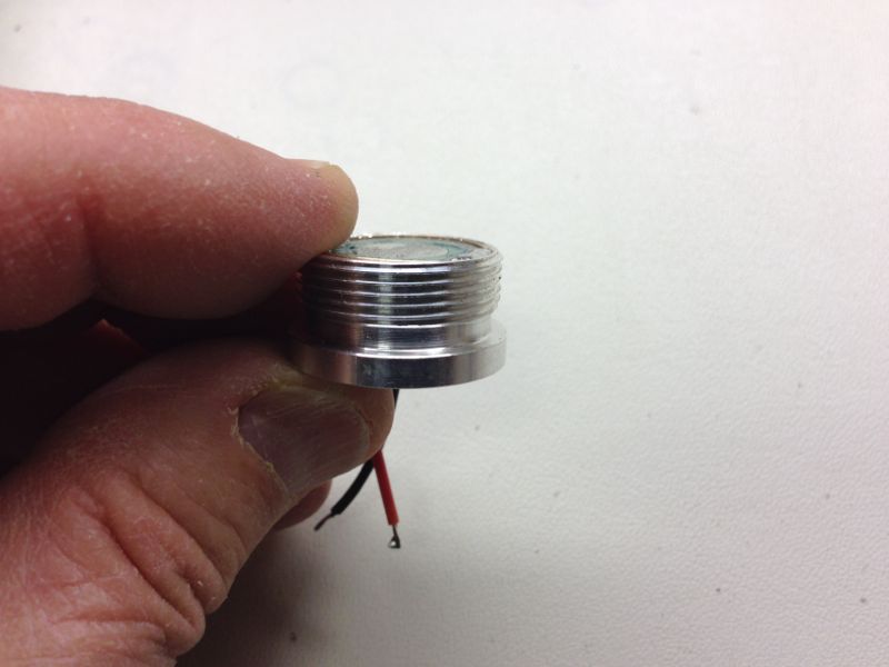
Side view of the completed assembly:
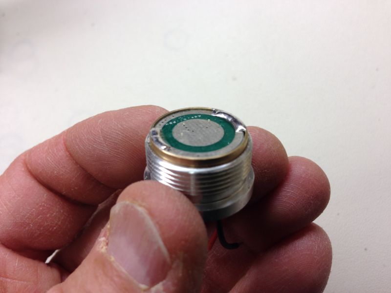
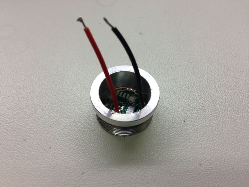
Top view of the completed assembly:
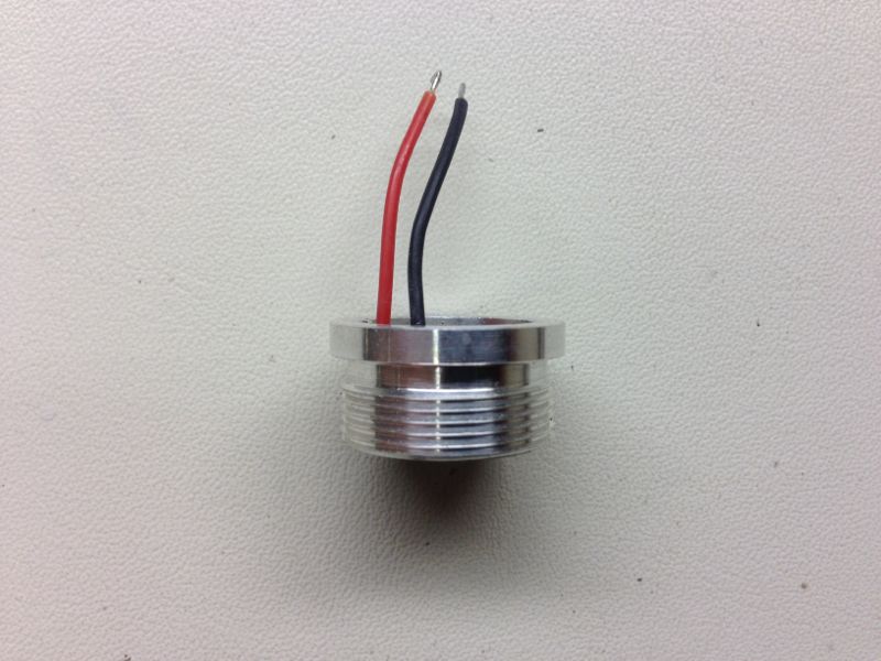
Another view:
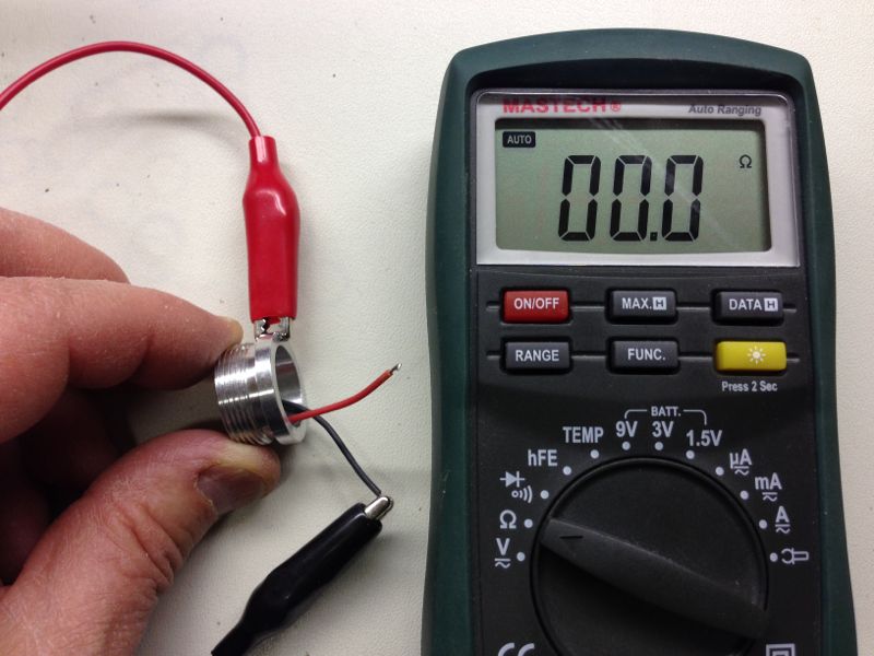
Using a DMM, test the negative side of the circuit for continuity. The reading should be zero ohms.
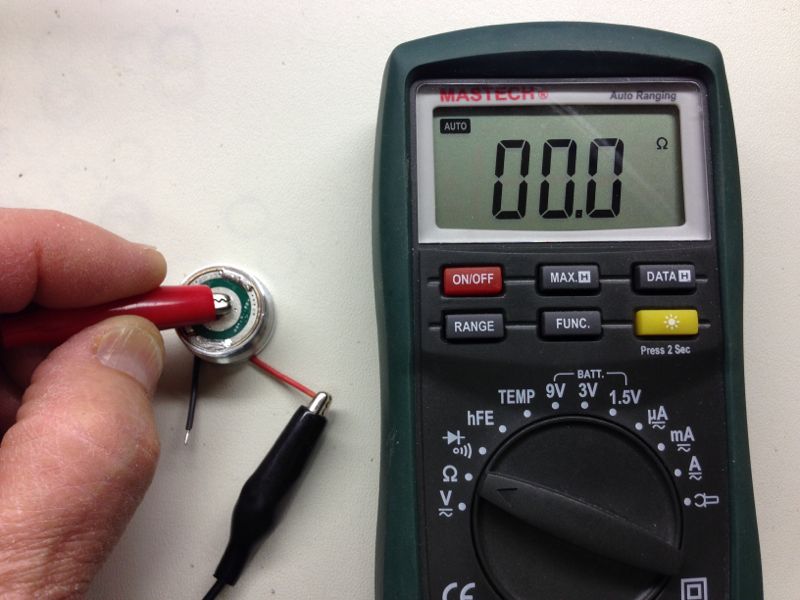
Test the positive side of the circuit for continuity. The reading should be zero ohms.
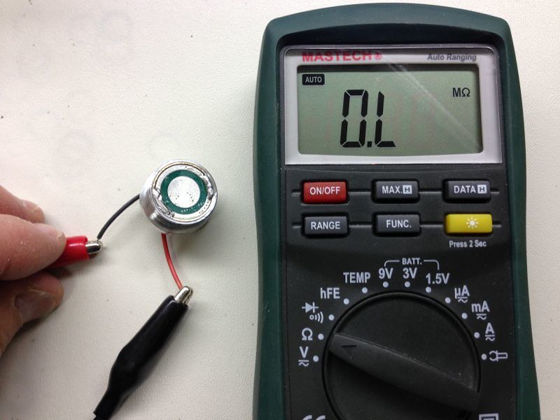
Finally, check the circuit for a short. The reading should be infinite or "over limit" ohms.
You are now ready to connect the battery contact board and pill assembly to your driver. I've posted a tutorial here about soldering a driver and pill assembly to a diode, but most of the instructions are similar.
Enjoy! :beer:
First, remove the nubs from the sides of the board with sandpaper or a small file:
Next, insert the board, wire side first, into the side of the brass ring with the recess:
Push the driver board completely into the recess in the ring:
Solder a small spot on the negative board trace next to the brass ring about 1/4" wide. Ensure that the solder has wetted both the board and the ring:
Solder a similar spot on the board 180 degrees from the first spot:
Wire side view of the finished subassembly:
Place the brass ring & board subassembly, tapered side first, into the recess in the pill:
Lightly press the brass ring & board subassembly into the pill recess until is evenly spaced above the pill:
Using pliers, gently squeeze the brass ring & board subassembly into the pill recess. Work your way around the pill to push the ring evenly and completely into the pill:
Side view of the completed assembly:
Top view of the completed assembly:
Another view:
Using a DMM, test the negative side of the circuit for continuity. The reading should be zero ohms.
Test the positive side of the circuit for continuity. The reading should be zero ohms.
Finally, check the circuit for a short. The reading should be infinite or "over limit" ohms.
You are now ready to connect the battery contact board and pill assembly to your driver. I've posted a tutorial here about soldering a driver and pill assembly to a diode, but most of the instructions are similar.
Enjoy! :beer:


