djQUAN
0
- Joined
- May 27, 2013
- Messages
- 1,154
- Points
- 63
Magnetic battery connectors allow you to temporarily attach wires to new/untabbed/unusual size batteries without soldering. I use them to connect hobby RC chargers or other electronic stuff to cylindrical rechargeable batteries.
You can also use magnets and just stick alligator clips to them but where's the fun in that?
Here's how I made mine.
Start by gathering items that you'd need. These are: silicone wire (I used 16ga), neo magnets from FT (link), a couple short piece of heatshrink, and your connector of choice.

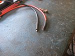
Start by stripping a short length of the wire end, tin the strands and add a length of heatshrink. (I'll explain what it's for in a minute)

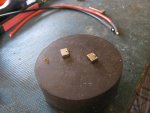
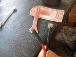
Here's the tricky part. Stick the magnet onto a big piece of iron and tin a small area on the side. The large iron holds the magnet and absorbs the heat preventing it from demagnetizing. Soldering iron tips are coated with iron therefore it can get attracted to the magnet so be aware of that.

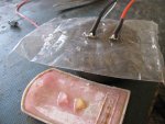
Clean with IPA to remove flux residue for the adhesive to stick well in the next step and solder the wires very quickly by simply heating them together to stick.

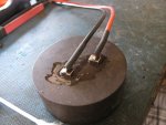
This is what the heatshrink is for. Since silicone is highly inert, adhesives won't stick to it. The heatshrink gives the 2 part epoxy something to hold onto and acts as strain relief.

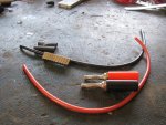
This is what they should look like once the epoxy is added to keep the wires in place. You can also add your connector to the other end of the wires after this step.

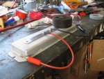
To make it cure faster and harder, I use a big a$$ resistor and run power into it to make it heat up to about 40degC then stick the magnets to a steel ruler and put it on the makeshift hotplate.

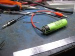
Here it is completed. Makes a convenient connector for charging/testing odd size batteries.

You can also use magnets and just stick alligator clips to them but where's the fun in that?
Here's how I made mine.
Start by gathering items that you'd need. These are: silicone wire (I used 16ga), neo magnets from FT (link), a couple short piece of heatshrink, and your connector of choice.
Start by stripping a short length of the wire end, tin the strands and add a length of heatshrink. (I'll explain what it's for in a minute)
Here's the tricky part. Stick the magnet onto a big piece of iron and tin a small area on the side. The large iron holds the magnet and absorbs the heat preventing it from demagnetizing. Soldering iron tips are coated with iron therefore it can get attracted to the magnet so be aware of that.
Clean with IPA to remove flux residue for the adhesive to stick well in the next step and solder the wires very quickly by simply heating them together to stick.
This is what the heatshrink is for. Since silicone is highly inert, adhesives won't stick to it. The heatshrink gives the 2 part epoxy something to hold onto and acts as strain relief.
This is what they should look like once the epoxy is added to keep the wires in place. You can also add your connector to the other end of the wires after this step.
To make it cure faster and harder, I use a big a$$ resistor and run power into it to make it heat up to about 40degC then stick the magnets to a steel ruler and put it on the makeshift hotplate.
Here it is completed. Makes a convenient connector for charging/testing odd size batteries.