Welcome to Laser Pointer Forums - discuss green laser pointers, blue laser pointers, and all types of lasers

LPF Donation via Stripe | LPF Donation - Other Methods

Links below open in new window

ArcticMyst Security by Avery

How does my wiring look?

Joined
Feb 19, 2009
Messages
879
Points
18
ello all,

I dont post much, but when I do, its usually because I need help with something and dont want to risk ruining any of my components.
Today, I would simply like to make sure my wiring makes sense.

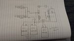
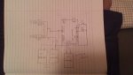
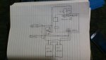
Im using two 445nm Laser Diodes, both using laser drivers and being driven at approx. 1.25A each (They are wired in parallel). They put out a little more than 1W of power each. Im using two 3.7V 1300mAh lipo batteries in series to run these. Ive hooked the lasers up in parallel with the 2 lipos in series and it works just fine, now im trying to incorporate it into the Arduino to be able to turn them on and off with a momentary pushbutton.
I am unsure of whether or not ill need a transistor. I thought that if I supplied the lasers with their own power source and drivers, the Arduino wont have to worry about limiting current.

So here is the drawing...I apologize if it may look a little messy. Ill figure out the code later, I just want to be sure that the wiring will work. Also, note that pins; 5,7, and 8 are shaded in because they are already being used to drive servos.

[URL=http://s597.photobucket.com/user/mattmagic100/media/Mobile%20Uploads/2

Thank you for your help!
Matt


Joined
Oct 5, 2013
Messages
522
Points
28
2012-06-30213603.jpg


Is this what you are trying to post?

I'm guessing not, but your image doesn't work.
 
Last edited:
Joined
Feb 19, 2009
Messages
879
Points
18
Yeah, thats not it. Thank you for trying though! I dont know why I couldnt get the actual photo though. Ill try it again when I get home.
 
Joined
Apr 26, 2010
Messages
4,175
Points
83
Well to link a URL, it needs to look like this, though you need an "=" after the "URL" and before the quotes, for it to work.

[URL"www.examplewebsite.com"]www.examplewebsite.com[/URL]

test

The above is a link going to what you posted, but neither that link, nor your username, exists according to Photobucket :p

If you want to post an image, you just put the following, with a "/" before the second set of "IMG" still in the brackets.

test.jpg[IMG]
 
Last edited:
Joined
Feb 19, 2009
Messages
879
Points
18
I know how to upload pictures but for some reason it didnt want to work off of my Microsoft Surface even though Ive done it before. Not only that, but photobucket seems to be acting strange as well.

Anyway, I think I got it....

If anyone knows anything about Arduino, I could use some input on the wiring.
The code I can handle.

Thank you!
 

Attachments

  • laser diagram.jpg
    laser diagram.jpg
    30.2 KB · Views: 114
Joined
Jul 4, 2012
Messages
2,834
Points
63
the image is so small i cant make it out... would you like to try again for $.25? Hehe im just joking around of course :)
 
Joined
May 14, 2013
Messages
3,438
Points
0
Looks like its wired like a Christmas tree :crackup: Haha just kidding. Yes larger picture please.

Alan
 
Joined
Feb 19, 2009
Messages
879
Points
18
Dammit, sorry guys...
Let me try again...


I got a tip from someone on the Arduino forum,
"You connected the 8.4V to Arduino Uno input pin, the Atmega 328 will gone in no time, and if you press the pushbutton, you will short the positive and negative of the 2 lipos in series, the battery will blow up."

If this is the case, how would you guys go about this wiring? Any tips?
 

Attachments

  • phpKuiyuyPM.jpg
    phpKuiyuyPM.jpg
    51.2 KB · Views: 181
Joined
Aug 14, 2013
Messages
2,655
Points
63
If your drivers have TTL inputs, attach those to one of the digital pins. Otherwise you will definitely need to
switch them using a transistor.

  • The batteries would connect to GND (-) and VIN (+).
  • The switch should connect between your input pin and a GND pin.
  • The resistor is unneeded. Just enable the internal pullup resistor in the sketch.
 
Joined
Feb 19, 2009
Messages
879
Points
18
If your drivers have TTL inputs, attach those to one of the digital pins. Otherwise you will definitely need to
switch them using a transistor.

  • The batteries would connect to GND (-) and VIN (+).
  • The switch should connect between your input pin and a GND pin.
  • The resistor is unneeded. Just enable the internal pullup resistor in the sketch.


If I connected the batteries to Vin, wouldnt that destroy the Arduino? I thought I needed a separate power source for the arduino. The two in series are for the lasers and the lone battery powers the Arduino.

Could I keep the resistor instead of enabling the inboard pullup to make coding easier?

Thanks for your response!
 
Joined
Aug 14, 2013
Messages
2,655
Points
63
If I connected the batteries to Vin, wouldnt that destroy the Arduino? I thought I needed a separate power source for the arduino. The two in series are for the lasers and the lone battery powers the Arduino.

No. It will handle up to 20V just fine.

Could I keep the resistor instead of enabling the inboard pullup to make coding easier?

You could, but why? It's only one line of code. digitalWrite (pin, HIGH);
Right after setting the pinmode
 
Joined
Feb 19, 2009
Messages
879
Points
18
No. It will handle up to 20V just fine.


You could, but why? It's only one line of code. digitalWrite (pin, HIGH);
Right after setting the pinmode


Ahh okay. However, Im going to be driving 2 servos as well which requires thebsame batter setup. And I know that servos for sure need a separate power supply. Could I drive the 2 lasers and 2 servos from those 2 batteries in series without putting the positive lead into Vin?

If not, im assuming I would need two sets of batteries for the lasers and two for the servos.

Regarding the pull up...I dont know but something about having that resistor there just makes it easier for me.
 
Joined
Aug 14, 2013
Messages
2,655
Points
63
Ahh okay. However, Im going to be driving 2 servos as well which requires thebsame batter setup. And I know that servos for sure need a separate power supply. Could I drive the 2 lasers and 2 servos from those 2 batteries in series without putting the positive lead into Vin?

Yes. Actually those will power everything unless you have really noisy servos. Most
Arduinos need at least 6V (7V recommended) to run, unless it happens to be a 3.3V
Arduino. Check the page for your model on arduino.cc. The servos are powered directly
from the batteries, not through the power pins on the Arduino, just like the lasers.

If not, im assuming I would need two sets of batteries for the lasers and two for the servos.

Only if there is noise and it is so bad that it's affecting the lasers

Regarding the pull up...I dont know but something about having that resistor there just makes it easier for me.

Then by all means use the external resistor. I'm just letting you know that there is a
resistor in the exact same place inside the Arduino in case you ever decide to use it. ;)
 
Joined
Feb 19, 2009
Messages
879
Points
18
Yes. Actually those will power everything unless you have really noisy servos. Most
Arduinos need at least 6V (7V recommended) to run, unless it happens to be a 3.3V
Arduino. Check the page for your model on arduino.cc. The servos are powered directly
from the batteries, not through the power pins on the Arduino, just like the lasers.


Only if there is noise and it is so bad that it's affecting the lasers


Then by all means use the external resistor. I'm just letting you know that there is a
resistor in the exact same place inside the Arduino in case you ever decide to use it. ;)


So the 2 batteries in series should be enough to drove the lasers, servos, and power the arduino, correct?
By connecting the positive lead of the battery (in series) to the lasers and servos as well as the Vin pin, would that not be like powering the lasers and servos from the board?
*im sorry for these annoying questions, I just want to be sure I understand right before I risk destroying hundreds of dollars worth of components.*

My servos alone are slightly noisy, but I dont believe its anything irregular from a regular servo.

Im going to draw up another diagram in a few hours and post it on here to be sure im getting it right.
Youre also saying there is no need for the 3rd lipo that I have separately powering the Arduino, correct? Because the 2 lipos in series is enough.

Haha, I understand. And there is a good chance ill probably just enable the pullup in the Arduino, but its a reasurring thing to see the resistor in front of me, haha :p.

Also, would require an NPN or a PNP transistor?

Thank you so much for your help!
:)
 
Last edited:
Joined
Feb 19, 2009
Messages
879
Points
18
Here is what I believe I think you're talking about with the wiring. Let me know what you think.

I'm not entirely sure that I wired the transistor right...

Thank you!
Matt
 

Attachments

  • phpJHoTseAM.jpg
    phpJHoTseAM.jpg
    51.6 KB · Views: 116
Last edited:
Joined
Aug 14, 2013
Messages
2,655
Points
63
Getting there. You're sure there are no TTL inputs on the drivers? Otherwise, your battery connections to the Arduino are correct. The negative on the drivers should connect directly to the battery negative. If the servos draw more than an amp, then the same goes for them as well. The connectors on the Arduino can only handle an amp or they will overheat. The Atmega328 itself can only sink 40mA on any one pin (200mA total).

The rest would be better addressed in an electronics or Arduino forum. Even better would be for someone to sit down with you and go over some electronics fundamentals.


Top