Welcome to Laser Pointer Forums - discuss green laser pointers, blue laser pointers, and all types of lasers

LPF Donation via Stripe | LPF Donation - Other Methods

Links below open in new window

ArcticMyst Security by Avery

Help please!

Joined
Nov 19, 2009
Messages
16
Points
0
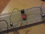
HIMNL9, thank you very much for the great picture! I will take a trip to my proffesor tomorrow, to get the additional elements and to put the circuit together. It seems, like you said... The circuit gets wrong at the regulation part. ADJ is connected to the control point and from there to the laser in my version, so that could be the problem!
And, does this circuit work with every DVD/CD burner diode? Because every of the "victims" i had was different.

Oh, and one more off-topic question: Could one possibly arrange an array of leds through the cube beam splitters to form one singular beam; could the beam be powerful enough when focused, so it could atleast engrave plastic?

Anyway... looks like i will have to go and beg out another DVD burner... :D

:thanks:


HIMNL9

0
Joined
May 26, 2009
Messages
5,318
Points
0
If you mean the cubes in the sleds, they can be used for combine only 2 beams, cause they are polarized beam splitter/combiners (basically, the 45 degrees face is a polar miror ..... it reflect the light polarized in one plane, and left pass the light polarized in the other) ..... if you have one beam with horizontal polarization, and one with vertical polarization, you can use it and combine the two beams in a single one, that contain both the polarizations ..... but it does not work with more than 2 beams, cause if you try to pass the combined beam in another cube, it split again the 2 polarized beams.
 
Joined
Nov 19, 2009
Messages
16
Points
0
If you mean the cubes in the sleds, they can be used for combine only 2 beams, cause they are polarized beam splitter/combiners (basically, the 45 degrees face is a polar miror ..... it reflect the light polarized in one plane, and left pass the light polarized in the other) ..... if you have one beam with horizontal polarization, and one with vertical polarization, you can use it and combine the two beams in a single one, that contain both the polarizations ..... but it does not work with more than 2 beams, cause if you try to pass the combined beam in another cube, it split again the 2 polarized beams.

Ah... There goes my idea of a cheap led laser...
 
Joined
Nov 19, 2009
Messages
16
Points
0
HIML9, one question... Would it be very critical for the diode if i run the driver from a normal 9v alcaline battery? 9v block that is...:undecided:
 
D

Deleted member 8382

Guest
There is no problem in using 9 or even 20V. This is a current regulator, the current on the diode won't change no matter the input voltage as long as it is between the driver limits. For the LM317 the limits are something like 5-30V, 9V is NO PROBLEM.

Btw, I just realized I already answered that above...
 
Joined
Nov 19, 2009
Messages
16
Points
0
Great!

I've read Sam's Laser FAQ.. as it seems, the diode looses efficiency with higher temperatures. My diode shined very well until i shut it down and started it again.
Looks like that when i was setting the current, diode heated up and shined on that current for the temperature. When i shut it down, it cooled and when i've put it back on, the driver was set on too much current, and COD blew it. It allso seems that ESD makes them even more sensitive/if not dead to COD. I really should have taken more care and preparations :eek::eek:
 
Joined
Nov 19, 2009
Messages
16
Points
0
One more question... Why do i have to connect 2 wires together, on the pot? I mean... I don't see any difference, or am i missing something?
 

HIMNL9

0
Joined
May 26, 2009
Messages
5,318
Points
0
The question about if connect 2 wires or not, on the pot, is controversial, but is not fundamental ..... both the systems, using the central and one side and left the other side open, or connect one of the sides to the central and use this and the other side, will work at the same way, at the end ..... i personally, when i use a pot / trimmer as variable resistor, prefer to connect the unused side to the central, cause in this way, if for some reasons the trimer get broken (the cursor, i mean), i don't end with an opened circuit, and for some applications, open circuits are dangerous ..... but this is just a personal preference.
 
Joined
Nov 19, 2009
Messages
16
Points
0
i personally, when i use a pot / trimmer as variable resistor, prefer to connect the unused side to the central, cause in this way, if for some reasons the trimer get broken (the cursor, i mean), i don't end with an opened circuit, and for some applications, open circuits are dangerous .....

Good point,:thanks:
 
Joined
May 31, 2009
Messages
3,239
Points
63
i personally, when i use a pot / trimmer as variable resistor, prefer to connect the unused side to the central, cause in this way, if for some reasons the trimer get broken (the cursor, i mean), i don't end with an opened circuit, and for some applications, open circuits are dangerous .....

Too true.. only reason I do that really..
 
Joined
Nov 19, 2009
Messages
16
Points
0
Something's wrong with my driver now. It's wired correctly in the way HIML9 posted it, same values, only the trimmer is 100Ohm. I've allso built the test load (4 diodes in series with a pot set to 1 ohm), and when i measure the voltage at the test load, i get ~28mV -> 28mA... That's when the driver is set to max. I tryed to fix it using different values of resistors, it just doesn't work like it should... I have some pictures, if they are of any help:


What the heck is wrong here? Oh, and the battery is new, it's voltage reading is 9,3V.:wtf:
http://img687.imageshack.us/i/28112009003.jpg/
http://img260.imageshack.us/i/28112009004y.jpg/
http://img405.imageshack.us/img405/9819/28112009i.jpg

I'm thinking it could be the lm317.. But the voltage between OUT and ADJ is allways around 1,25v, like the datasheet said, so there shouldn't be any problem! :thinking:
 
Last edited:

HIMNL9

0
Joined
May 26, 2009
Messages
5,318
Points
0
..... 4 diodes in series with a pot set to 1 ohm .....

You probably killed your pot :p

You need an 1 ohm 1 W (at least half watt, for low current), and pot / trimmers, usually, are 100mW .....

Also, ofcourse, you connected the load with the right polarity, right ?

BTW, the pics says me 404 file not found


Edit: now i see the pics ..... sorry, what exactly is this component in the circle ? ..... it look like an rf blocker, seen in this way .....

attachment.php
 

Attachments

  • driver-strange.jpg
    driver-strange.jpg
    101.5 KB · Views: 358
Last edited:
Joined
Nov 19, 2009
Messages
16
Points
0
It's a diode, just dyed silver... I connected the load with the right polarity and the pot still has resistance...
 

HIMNL9

0
Joined
May 26, 2009
Messages
5,318
Points
0
OK, first thing, check that the trimmer do right contact in the board (i have he same type of proto boards, and sometimes those springs inside the holes are not doing the right contact with trimmer pins ..... sometimes i had to solder short pieces of wire on the pins, or "squeeze" the trimmer pins until they become thin enough to pass all inside the holes and make contact, this way

attachment.php


The silver diode, you connected it at the output, right ? ..... check that the cathode is connected to the positive side (being all painted in silver, i cannot say from the pic if is connected right ..... anyway, for the test, you can also take it away)

The dummy load is made with 4 diodes and a resistor, all in series and ofcourse with all the diodes connected anode-cathode ..... the side of the load that go to the positive output of the driver, here, is the anode, check also this just for be sure.

And no, using a pot / trimmer as 1 ohm load is not the good way, also if it still measure some resistance, a normal DMM cannot measure correctly 1 ohm, in normal conditions (on a commercial DMM, when you read 1 ohm, you can have from 0.3 to 1.5 ohm, depend from the precision of the instrument ..... and cheap ones are never precise, in these conditions) ..... for measure values so low, you need a milliohmeter ..... so, please use a resistor, also an old resistor from some mangled circuit, or a group of resistors in parallel, anything is better than a potentiometer, for that use, seriously ..... if you cannot find the right value, use different values in parallel (like, 2 of 2.2 ohm, or 3 of 3.3 ohm, or different ones) ..... this just for check if your driver really work in the right way ..... also if in this way the resistance is a bit more high, at least in this way you can check if your LM317 is still working, or if there's something wrong in the circuit, or if the LM is broken .....

Other than this, i can't imagine, at the moment, why your driver don't work correctly.

Edit: someway the pic disappeared ..... i reloaded it, and now seem ok.
 

Attachments

  • trimmers.jpg
    trimmers.jpg
    92.1 KB · Views: 406
Last edited:
D

Deleted member 8382

Guest
Wait. When you say that the driver is "to the max" you mean that the pot is "to the minimum" right?


Top