Welcome to Laser Pointer Forums - discuss green laser pointers, blue laser pointers, and all types of lasers

LPF Donation via Stripe | LPF Donation - Other Methods

Links below open in new window

ArcticMyst Security by Avery

Help With Ophir Head and Panel Meter-1 Battery


Joined
Aug 15, 2009
Messages
1,443
Points
48
The Ophir head needs a symmetrical power supply, you could split the voltage of the battery or use a DC-DC converter. Keep in mind that the output voltage of the head can only go up to the power supply voltage minus 2 volts.
 
Joined
Apr 27, 2011
Messages
159
Points
0
Thanks,
Can you please show me a schematic or picture. I really don't want to stuff up the thermopile. I have lm7805's and lm7806's. and want to power Both the Ophir head and dpm off the same battery. Thanks.

Chris
 
Joined
May 4, 2009
Messages
5,443
Points
113
Here is a diagram for you hope it helps ;)
Pay attention the the voltage and the polarity.

Here is the sheet that tells what is what.
p1016729.jpg


And here is a wiring diagram.
OphirMeterWiring.jpg
 
Last edited:

rhd

0
Joined
Dec 7, 2010
Messages
8,475
Points
0
I'm experimenting with the concept of using a 7805 and a 7810 to create a +5 and +10 output, such that the +5 could be used as the virtual ground, the +10 as (essentially) the +5 for the Ophir, and the true GND as the -5 for the Ophir.

I don't know if this will work as theorized, but I'll let you know how it works out this weekend. This would make it relatively simple to use one power source for all of the above, with minimal components.
 
Joined
Sep 20, 2008
Messages
17,622
Points
113
Here is a diagram for you hope it helps ;)
Pay attention the the voltage and the polarity.

And here is a wiring diagram.
OphirMeterWiring.jpg
As I've already stated in another Thgread....the junction of the
brown wire and the gray wire needs to be tied together in that
drawing or the head won't work...


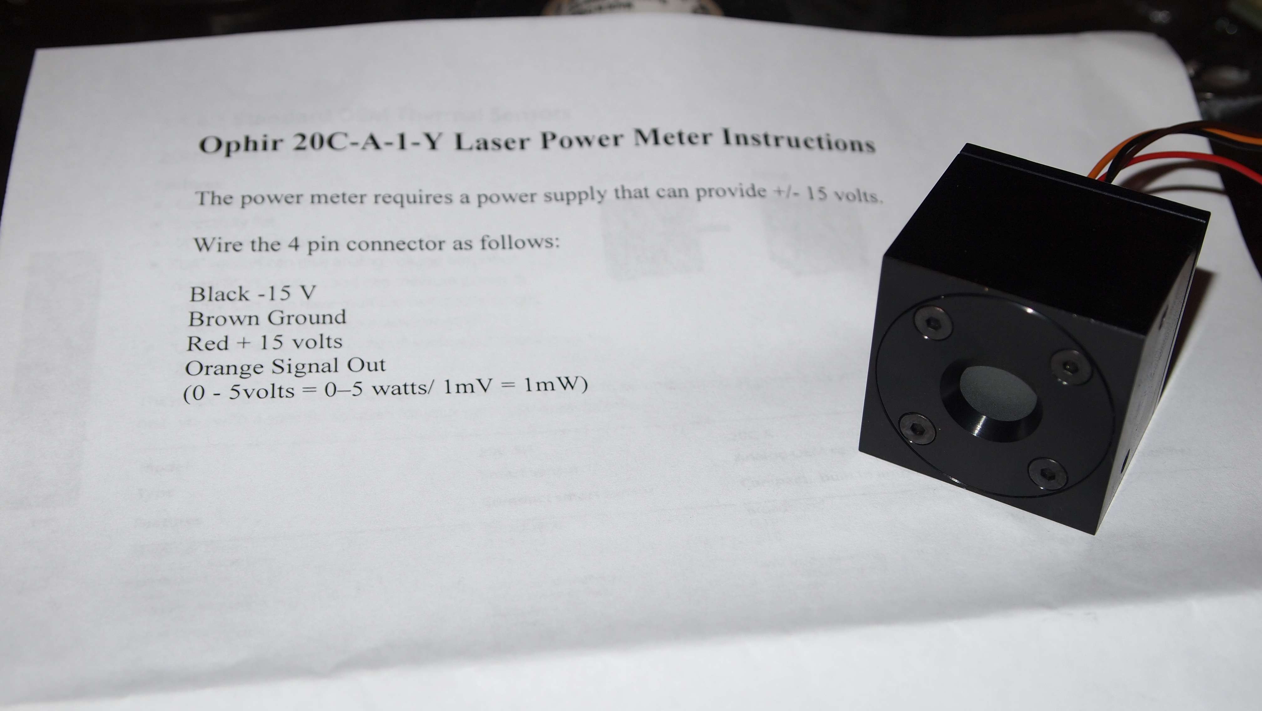
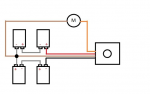
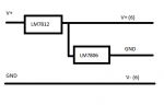
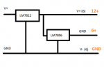
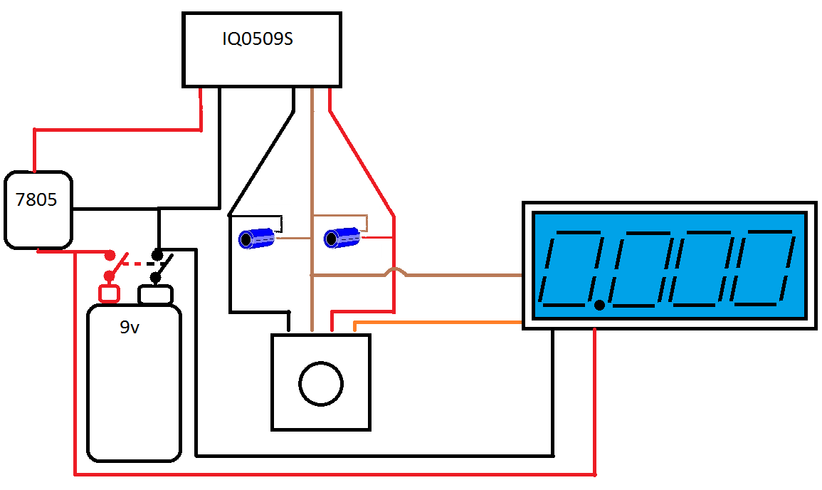
hey guys, I have brought an Ophir 20C-A head and digital panel meter, but I read I cannot hook them up to one battery in parallel? Could someone please show me how I could run these two components off the same battery.

Cheers,
Chris

If you are intent to run both the OPHIR Head and a DPM from
a single supply you WILL need a +/- DC/DC converter fro the
Head +/- split supply and a positive voltage regulator for the
voltage that your DPM requires....

BTW a 9Volt batter will not run very long powering the DC/DC
converter.... the OPHIR Head and the DPM....


I'm experimenting with the concept of using a 7805 and a 7810 to create a +5 and +10 output, such that the +5 could be used as the virtual ground, the +10 as (essentially) the +5 for the Ophir, and the true GND as the -5 for the Ophir.

I don't know if this will work as theorized, but I'll let you know how it works out this weekend. This would make it relatively simple to use one power source for all of the above, with minimal components.

Sorry... I can't see it working due to common grounds.....
A Schematic of your setup would make an evaluation
much clearer...

The OPHIR head requires more than 5volts IIRC....


Jerry
 
Last edited:

rhd

0
Joined
Dec 7, 2010
Messages
8,475
Points
0
This will make Jerry really happy :)

attachment.php


This is not a schematic, but it shows the basic concept. I don't know that it will work either. However, 5V +/- is enough for an Ophir if you check out the datasheet.

attachment.php
 

Attachments

  • Untitled.png
    Untitled.png
    35.8 KB · Views: 1,309
  • theory.png
    theory.png
    4.8 KB · Views: 1,163
Last edited:

jib77

0
Joined
Jun 19, 2010
Messages
718
Points
0
The following circuit splits any voltage input in half ... i.e. a 12V wall wart will give you +6 and -6VDC. You can still use two 9V batteries for +9/-9V, but with a simple hookup. To use a panel meter on the same supply, you simply hook up a 7805 or LM1117/5V to the +V and virtual ground and run that to the meter.

Schematic here:
http://laserpointerforums.com/f67/driver-circuit-thread-65149.html#post935277

6066-dualrailhookup.png
 
Joined
Sep 20, 2008
Messages
17,622
Points
113
This will make Jerry really happy :)

attachment.php


This is not a schematic, but it shows the basic concept. I don't know that it will work either. However, 5V +/- is enough for an Ophir if you check out the datasheet.

attachment.php
Thanks... that will help the members that were not aware...

BTW... It has nothing to do with making me happy...
It has to do with the proper way of showing a connection
on that drawing... Two different color traces are not normally
connected together unless specified.

As to your basic concept circuit you will see clearly that it
will not work once you draw in the Ground connections
required by the Positive regulators...

All I see is from top to bottom... [+12] [+6] [Ground]


The following circuit splits any voltage input in half ... i.e. a 12V wall wart will give you +6 and -6VDC. You can still use two 9V batteries for +9/-9V, but with a simple hookup. To use a panel meter on the same supply, you simply hook up a 7805 or LM1117/5V to the +V and virtual ground and run that to the meter.

Schematic here:
http://laserpointerforums.com/f67/driver-circuit-thread-65149.html#post935277

You would need a Low Drop Out 5V Regulator if you are
supplying only 6V to it. The 7805 would never regulate
the 6Volts from your PCB to 5Volts properly... if using
a 12volt wall wart

Increasing the the input voltage to your PCB to above
16Volts would allow you to use the 7805..

BTW... I would supply a regulated input voltage to your
circuit just to keep the voltages to the OPHIR head stable.


Jerry
 
Last edited:

rhd

0
Joined
Dec 7, 2010
Messages
8,475
Points
0
As to your basic concept circuit you will see clearly that it
will not work once you draw in the Ground connections
required by the Positive regulators...

All I see is from top to bottom... [+12] [+6] [Ground]

Yep, that's what you'd have. The question is whether the +6V can function as a virtual ground, with the actual ground functioning as a -6V and the +12 functioning as a +6V relative to it.

More like this:
attachment.php


But - like I said, just testing it out. I don't know whether the concept is solid. It sounds like it might not be. That's cool. It would have been a simpler approach had it worked.

You would need a Low Drop Out 5V Regulator if you are
supplying only 6V to it. The 7805 would never regulate
the 6Volts from your PCB to 5Volts properly... if using
a 12volt wall wart

You could probably just hook the 7805 to the source +12V and GND.
 

Attachments

  • Untitled.png
    Untitled.png
    5.7 KB · Views: 1,273
Last edited:
Joined
Sep 20, 2008
Messages
17,622
Points
113
This is not a schematic, but it shows the basic concept. I don't know that it will work either. However, 5V +/- is enough for an Ophir if you check out the datasheet.

attachment.php

Hey RHD....

I'm impressed...
I just built this circuit and it does seem to work...

The only problem is that between the Ground and +6V
in your drawing above there is no regulation and the
current supplied is very low...

Here are some readings I just took dropping in different
resistors I had laying around..

Res........ mA........Voltage

~ .......... 0 .......... 6.33
10K........ 0.6........ 6.34
4K7........ 1.4........ 6.60
3K3........ 2.4........ 7.59
2K2........ 3.3........ 7.12
1K5........ 4.1........ 6.18
1K0........ 5.1........ 4.96
330........ 7.4........ 2.37


Jerry
 
Last edited:

jib77

0
Joined
Jun 19, 2010
Messages
718
Points
0
You would need a Low Drop Out 5V Regulator if you are
supplying only 6V to it. The 7805 would never regulate
the 6Volts from your PCB to 5Volts properly... if using
a 12volt wall wart

Increasing the the input voltage to your PCB to above
16Volts would allow you to use the 7805..

BTW... I would supply a regulated input voltage to your
circuit just to keep the voltages to the OPHIR head stable.

Jerry

Yup ... I used a fixed 5V LM1117 in my build and it works great with a switchmode regulated 12V wall wart. I scoped the output and there was minimal ripple on the +6V rail (~25mV P-P) and almost dead flat on the virtual ground.
 
Joined
Apr 27, 2011
Messages
159
Points
0
hey guys, I hope this isn't considered a necropost :?
Anyway I was wondering if you guys could please check this drawing.
I just need to check:
Whether it will even work!
If 'piggybacking' the dpm power off the 9v has any affect on the accuracy of the ophir head,
and the polarity and value of the capacitors

7143018.png


This is the dc/dc converter:XP POWER|IQ0509S|DC/DC CONVERTER, SEMI REG, , DUAL | element14 Australia
Datasheet: http://datasheet.octopart.com/IQ0509S-XP-Power-datasheet-10025710.pdf

Thanks :)
 
Last edited:
Joined
Sep 20, 2008
Messages
17,622
Points
113
hey guys, I hope this isn't considered a necropost :?
Anyway I was wondering if you guys could please check this drawing.
I just need to check:
Whether it will even work!
If 'piggybacking' the dpm power off the 9v has any affect on the accuracy of the ophir head,
and the polarity and value of the capacitors

7143018.png


This is the dc/dc converter:XP POWER|IQ0509S|DC/DC CONVERTER, SEMI REG, , DUAL | element14 Australia
Datasheet: http://datasheet.octopart.com/IQ0509S-XP-Power-datasheet-10025710.pdf

Thanks :)

1) We don't know the value or voltage of your Caps

2) It is better to tap off the battery than the DC/DC Converter
assuming that your DPM has a 9Volt supply requirement.

3) The capacitors on the output of your DC/DC converter are
connected in reverse.


Jerry


Top